Posts

Showing posts with the label with

Gionee W900 The first smartphone with a dual screen 1080p

Image
The Chinese company Gionee, known mainly for its thinnest smartphone Elife S5.5 and Elife E5.1, is preparing another interesting device. The device, made in unusual for modern smartphones clamshell, was seen on the website of the Agency for certification of Chinese telecommunications equipment (TENAA). This model will be the world's first smartphone equipped with two screens with a resolution of 1080p. Diagonal inner and outer screens is 4 inches. Given the resolution of 1080 x 1920 pixels it gives quite a high density of 550 ppi. The device runs on Android 4.4 KitKat, built on a quad-core processor with a clock speed of 1.5 GHz, equipped with a 13-megapixel main and a 5-megapixel front-facing camera, 2 GB of RAM and 16 GB of internal memory and supports network LTE. The thickness of the model is 14.8 mm, and weight - 172 grams. While nothing is known about when to begin selling Gionee W900 . In any case, the smartphone will be released in China and it is difficult to say whether h...
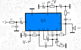
50W audio amplifier with ICs

Image
The above amplifier circuit based on IC is STK075G, and another equation that is STK084G, STK085, STK086G. and among ic I mentioned that I recommend using ic high supply voltage and high output power and good quality. You can see every ic datasheet at Alldatasheet.com above. Supply voltage between 20 to 55 Volt DC. Part List R1 = 1K R2 = 100R R3 = 100R R4 = 4.7R R5 = 56K R6 = 47R C1 = 1uF C2 = 470pF C3 = 100uF C4 = 100uF C5 = 1800pF C6 = 1uF C7 = 1800pF C8 = 0.047uF C9 = 100uF U1 = STK075G,  STK084G, STK085, STK086G

An LCD Clock Kit Suitable for Beginners with Open Source Arduino Firmware

Image
Simpleclock is an easy to assemble attractive 4-digit 7-segment LED display clock with temperature and alarm function. It is available in three display colors: Red, Blue and White. It comes as a kit of through-the-hole parts and can be soldered by any person with basic soldering experience. An attractive acrylic stand is included. [ ]

Simple Inverter with Two Transistors

Image
The series below is a simple inverter circuit that will change the voltage of 12v dc to 220v ac, with use drive transistor 32 as its tip. Inverter circuit is very simple and easy to assemble and is perfect for just starting to learn to assemble electronic circuits, you can use the transformer 2A to produce about 20 watts output. Do not forget to install coolers in its transistors. good luck.

DAC with MCS5 Microcontroller

Image
The figure below shows the Configuration DAC With artificial MCS51 Microcontroller National Semiconductor, capacitors C1, C2 and form a series of 12 MHz XTAL oscillator, capacitor C3 and resistor R1 form a series reset. Digital scale is given to the B1 to B7 (leg 5 to 12) in the IC DAC0800, the binary value of the digital scale was converted into an analog magnitude of the current at IOUT (ft 4 DAC0800) and IOUT * (feet 2 DAC0800), then by IC Operational Amplifier LM741 flow is converted into voltage. The resulting voltage expressed by the formula shown in Figure below, in addition to depending on a digital scale weight value is given, this voltage depends on the size of Vref (DAC0800 14 feet). figure.1 DAC With MCS5 Microcontroller C3 is mounted on leg 16 and ground is useful for stabilizing the voltage generated. DAC0800 and LM741 using voltage source +12 Volt and -12 Volt, is somewhat different from the voltage that is usually used for digital circuits, so that digital signals can ...

Low Voltage Amplifier Circuit with IC BA518

Image
This Circuit use IC BA518 or you can use the IC BA547 , this is low mono power amplifier. Maximum power output 5W . But this is also low voltage amplifier with minimum voltage require 2 Volt. And maximum voltage 12 Volt .Impedance 8 Ohm , support small speakers. Circuit schematic below : Click image to view large Troubleshooting if circuit not working  : Check components are can be use or not , also check the use avometer or other measuring instrument.  Check the voltage on each component.   If there is a voltage that has not been entered on the components, then see if there is a broken line or short-circuit PCB , thereb inhibiting the incoming flow. Then check  whether the input and output cables are still good or not.

Schematic Audio Amplifier with IC AN313

Image
This schematic very suitable applied on small speakers. Because the maximum output is 3W and the minimum voltage is 12 Volt  , this will make speaker does not damage quickly. If you use speaker with impedance 8 Ohm , you must make parallel circuit speaker don't use series circuit. See This Schematic and datasheet IC AN313 below : Datasheet IC AN313 Vcc                = 12-20 V Pout               =  2x3 W RL                  = 8 Ohm Ft                   = 40hz -18Khz Icco                = 40 mA Package         = TABS6-16 Manufactered = MATSUSHITA Or you can call , Datasheetnya IC AN313

Stereo Audio Amplifier with IC TEA2024

Image
 The circuit above is based on IC TEA2024, package IC is SIP2-10 and manufactered by THOMSON. Circuit above can be applied anywhere as long as the speaker must be required , do not use powered speakers, it will make this circuit of hot , especially on the IC. So the use of powered speakers with the power output of this circuit. Technical Information : Minimum voltage : 6 Volts DC Maximum voltage: 18Volts DC Power Output       : 2 x 7 Watts Impedance           : 4 Ohms Currents               : 35 mA

90W Power Amplifier Circuit with Transistor 2N3055

Image
Using only four transistors in the quasi-complementary amplifier configuration, this transistor power amplifier circuit can deliver 90W of power into 4 ohm loads and at low cost. As shown in the transistor power amplifier circuit there are no expensive components in this circuit, except the power transformers and speakers. As shown in the diagram there are no expensive components in this circuit, except the power transformers and speakers. Input stage is formed by this two current driver directly raised a pair of transistors of the output stage. Transistor level end (2N3055) mounted on a heat sink to keep the lifetime of these devices. Supported by one source (of 80Vcc) at the output of the final stage, before the speaker, a capacitor is placed to block DC current, and just skip the audio signal. The power supply circuit 90 W audio power amplifier must be sufficient to provide current 1.5A per channel audio. Thus the power required to operate the stereo 3A and 6A is required for the fo...

DC motor driver with H Bridge IC L293D

Image
Making a DC motor driver with H-Bridge technique can use IC L293D as in the article "DC Motor Driver H-Bridge L293 (2 Motor DC)"is. DC motor driver L293D can be used to control the DC motor 2 pieces at once. DC Motor Driver L293D can be used to control a DC motor continuously or with a PWM technique. Dc motor driver circuit in the article "DC Motor Driver H-Bridge L293 (2 Motor DC)" only use IC L293D only. For more details see the following figure. Working system of DC motor driver L293D is to provide control signals in the form of logic or pulse to the input lines 1A - 1B for DC motor control M1 and the input 2A - 2B for the control of DC motor M2 with the following conditions: Input A Input B Motor DC 0 0 Motor silent 1 0 motor rotates counterclockwise 0 1 Motor berputer clockwise 1 1 Motor silent Description: Enable Input given a logic 1 to obtain such data in the table above.

Digital tone control with MAX5406

Image
The series will I make here is a series regulator of Volume, Bass, and Balance Trable Digital (Tone Control). The core of this circuit is an IC-type output from the Manufacturer Maxim MAX5406, while the IC is an audio processor that comes with the interface switch hit for Tone Control setting above. The circuit scheme is as follows: The scheme above uses very little supporting components and this makes can be made with a mini size of a matchbox only even if using all SMD components can be reduced in size by half for this time I will only give a simple layout made​​, following picture: layout components

Digital Clock with Timer and Solar Panel Regulator

Image
This is a combination digital clock timer and solar panel charge controller used to maintain a deep cycle battery from a solar panel. The timer output is used to control a 12 volt load for a 32 minute time interval each day. Start time is set using 9 dip switches and ends 32 minutes later. The 32 minute duration is set by selecting the 5th bit (2^5 = 32) of a 4040 binary counter (pin 2). The timer also has a manual toggle switch so the load can be manually switched on or off and automatically shuts off after 32 minutes. The time duration can be longer or shorter (8,16,32,64,128,256 minutes etc.) by selecting the appropriate bit of the counter. The timer circuit is shown in the lower schematic just above the regulator.   Basic Clock Circuit diagram The basic clock circuit (top schematic below) is similar to the binary clock (on another page) and uses 7 ICs to produce the 20 digital bits for 12 hour time, plus AM and PM. A standard watch crystal oscillator (32,768) is used as the tim...

LG PLDE P008A SMPS Power Supply Unit with Integrated Led Driver SCHEMATIC

Image
LG PLDE-P008A - LG PLDE-P008A-CKD Power Supply Unit with Integrated Led Driver - LG LCD TV - Circuit Diagram SCHEMATIC

Water level indicator with buzzer circuit

Image

Simple Bell Circuit with Two 555 Timers Project

Image
This is a Simple Bell Circuit with Two 555 Timers Project . This simple Bell circuit uses two 555 timers. The frequency is controlled by the capacitors that must be preserved almost identical in value to each other for best results. Fine tuning is done with R1 and R2. The decay time is controlled by R3.  Simple Bell Circuit Diagram

Multiplexer Switch with 4066 Circuit Diagram

Image
This is a switch circuit using a digital multiplexer 4066 Ic , their keys are ES8 ES1 to 4066 and each contains four switches. When the channel is selected first, and ES1 ES2 ES3 are closed and open, which prevents cross-over between the two channels is the grounding of the channel is not in use. The bandwidth of the multiplex circuit is about 8 MHz and the consumption is 1 mA. When the multiplexer circuit is connected to a load impedance of 75 Ω, the circuit will result in some loss of signal due to internal resistance of the keys. This can be compensated for by connecting an amplifier output. Multiplexer Switch with 4066 Circuit Diagram

Simple Programmable Electronic Dice with Numeric Display

Image
Here’s a simple programmable electronic dice with numeric display . This dice can be programmed using a 4-way DIP switch to display any random number between ‘1’ and ‘2,’ ‘1’ and ‘3,’ ….. or ‘1’ and ‘9.’ To obtain the desired dice range, inner switches A, B, C and D of DIP switch are to be set as per the table. For example, if you want the electronic dice to count from 1 to 8, close switches A and D and keep B and C open. On pressing switch S1, the display varies fast between ‘1’ and ‘8.’ When you release S1, the display stops shuffling and the last (latest) number remains on it. IC1 is a dual 4-input Schmitt trigger NAND gate 74LS13. Gate N1 is used as an oscillator built using resistor R2 and capacitor C1 to produce approximately 70kHz clock frequency, which is fed to IC2. Gate N2 loads data at the inputs of IC2. IC2 is a presettable binary counter (74LS191) with parallel loading facility. Whenever its pin 11 goes low, the data present at its inputs D through A (which is ‘0001’) appe...

Digital Clock with MM5314N

Image
Description  The digital clock of circuit, has as base one IC, the MM5314N, in which are contained all the circuits that need. The IC1 collaborates with six Display of common anode, that are not critically as materials. You can select what dimension, you want it is enough you adapt pins their in the circuit. The display are drive by a system of polyplexis and are drive by thirteen transistors. For timing the circuit, is used the frequency of network (50HZ). This solution is the simplest, that it is not best. For more constant frequency you can use a circuit that would be based on crystal, (it will be given shortly). For the clue of hour are used six display of 7 element common anode. The DS1-DS2, show the hours (decades-unit respectively), the DS3-DS4, show the minutes and DS5-DS6, the seconds. The common anode, for each display is drive by the collector of transistors Q8 until Q13. Individual led (a, b, c, d, e, f, g) the display, they are linked between them (parallel) and are dr...

VU Meter 1 Using with Transistor

Image
Here is a simple Electronic Circuit Project of VU Meter 1 with transistor Circuit. This is Simple Circuit of optical index of level of sound signals, adapted in various needs of user. It can be adapted in various levels of entry, regulated from trimmer TR1 (Level) - TR2 (Gain), then it is rectified by the D1-2 (cutting off of negative periods of signal-rectification) and drived to the main circuit of index, that it is constituted by D3...D13 , the transistors Q2-Q13 and the materials that exist around them.  VU Meter 1 Using with Transistor Circuit Diagram: The optical index him we take from the line of LED LD1-13. The each led turns on when the level is altered at 0,65V roughly. The requirements in current are 100 ma with complete index. We can add all units LED we want, always calculating the current where they will need the news LED. Parts List of  VU Meter 1 Using with Transistor :

Simple Tone Control Circuit with LM301A

Image
This circuit and a simple series circuit Tone Control. This circuit tone control with surgical Amp LM301A. The JFET 2N3684 feature provides a high input impedance and low noise for UN buffer zone opinion operational amplifier operated EQ type. Could you see in detail of the circuit following thus as below. link