Posts

Showing posts with the label AC

Basics of AC Servo

Image
  A "servo system" is a generic term used for an automatic control system. In other words a mechanism which adjusts itself during continued operation through feedback.   Servo control is a closed loop control system for electric motors. The servo system uses a sensor to sense motor position/speed. Servo control has a feedback circuit which changes the drive power going to motor according the control input signals and the feedback signals from sensors Three basic types of servo motors are used in modern servo systems: ac servo motors, based on induction motor designs; dc servo motors, based on dc motor designs; and ac brush less servo motors, based on synchronous motor designs. AC servomotors are typically permanent magnet synchronous motors that often have low torque-to-inertia ratios for high acceleration ratings. AC servomotors use integral encoders, integral resolvers, and integral tachometers for feedback signals.   Integral encoders contain attached encoders for angu...

DC to AC Inverter with IC CD4047

Image
This DC to AC inverter circuit work based on unstable multi vibrator does. In this circuit, IC CD4047 is chosen as a heart of unstable multivibrator, because this IC type gives a complementary output that has opposite phase to another ( pin 10 and 11 as seen in Figure 1), and has 50 % duty cycle that satisfy to generate a pulse for inverter. DC to AC Inverter with IC CD4047 Circuit Diagram

250 to 5000 watts PWM DC AC 220V Power Inverter

Image
Build a 250 to 5000 watts PWM DC/AC 220V Power Inverter  This is my schematic design of a Pulse Width Modulator DC/AC inverter using the chip SG3524 . I have built this design and using it as a backup to power up all my house when outages occur. If you like my work and intend to build the circuit don't forget to give me the 5 satrs :D and subscribe to me by clicking on the "follow" button so I know how many people benefit from the design, Thanks Notes: >The schematic circuit design is for a 250 watt output, while the pics are of my 1500 watts inverter that i built, to increase the power of the circuit you have to add more of the Q7 and Q8 transistors in parallel, each pair you add will increase your power by 250 watts, ex: to get 750 watts of power from the inverter you need to add in parallel 2 of Q7 and 2 of Q8 to the original design. >If you increase the power transistors you have to enlarge the T2 transformer to match the new needs, the circuit's ...

Indicator Consumption AC Load Circuit Diagram

Image
This is Indicator consumption AC Load Circuit Diagram . Some types of electronic equipment does not show that in fact they are consuming energy when they are plugged into an outlet. This pilot light is not required if the unit consumes less than 10 watts according to international standards. But if you turn off the equipment, will be contributing with nature and your pocket, reducing the bill. One way to detect the AC power being consumed, independent of the load is connected in series with a diode AC power supply. In this circuit 6A diodes have been used which can withstand a peak current of 200A is not repeated. Indicator consumption AC Load Circuit Diagram The voltage between the diodes serves as the voltage supply for the LED and circuit. To increase the sensitivity of the circuit, we used a voltage doubler consisting of C1, D7, D8 and C2 is used to double the voltage of D1-D6. Another advantage of this scheme is that both reduce by half waves of alternating current. Must use Schot...

Simple 300mA DC to AC converter Circuit Diagram

Image
     This is the Simple 300mA DC to AC converter Circuit Diagram. This circuit was used to provide battery backup to a device that had an AC (output)wall transformer. Due to the quasi sine-wave output and imprecise 60Hz output frequency, some devices might not work pro perly. Peak output is the DC input voltage minus about 20 ohms drop. Use bigger output MOSFETS for more current output.[link]  Simple 300mA DC to AC converter Circuit Diagram

Build a 250 to 5000 watts PWM DC AC 220V Power Inverter

Image
Build a 250 to 5000 watts PWM DC/AC 220V Power Inverter  This is my schematic design of a Pulse Width Modulator DC/AC inverter using the chip SG3524 . I have built this design and using it as a backup to power up all my house when outages occur. If you like my work and intend to build the circuit don't forget to give me the 5 satrs :D and subscribe to me by clicking on the "follow" button so I know how many people benefit from the design, Thanks Notes: >The schematic circuit design is for a 250 watt output, while the pics are of my 1500 watts inverter that i built, to increase the power of the circuit you have to add more of the Q7 and Q8 transistors in parallel, each pair you add will increase your power by 250 watts, ex: to get 750 watts of power from the inverter you need to add in parallel 2 of Q7 and 2 of Q8 to the original design. >If you increase the power transistors you have to enlarge the T2 transformer to match the new needs, the c...

1000W DC AC Pure Sine Wave Power Inverter Circuit Diagram

Image
DC-DC step-up part of the circuit RU190N08 Power circuit board SPWM drive plate TDS2285 IC

3000 watt power inverter 12V DC to 230V AC

Image
  3000 watt power inverter 12V DC  to  230V AC Circuit Diagram of 3000 watt power inverter 12V DC  to  230V AC Fig. 2: Sine-wave voltage and conventional square wave voltage with both 230 Volt rms Fig. 3: Square wave voltage with duty cycle 25% for 230 Volt rms ("modified sine") PCB Layout: 3000 watt power inverter 12V DC  to  230V AC   Component Placement: 3000 watt power inverter 12V DC  to  230V AC fig.: output voltage with no load or inductive load. fig.: resistor 0,001 Ohm made of high-grade steel sheet metal Control electronics | 3000 watt power inverter 12V DC  to  230V AC fig.: control electronics on strip hole plate (previous version) and PCB of the "professional edition" Assembly of the mosfet-transistors on the heat sink | 3000 watt power inverter 12V   DC  to  230V AC fig.: heat sink, mosfet transistors, connections. Final assembly | 3000 watt power inverter 12V DC  to  230V AC fig.: 15...

Varying Brightness AC Lamp Circuit Diagram

Image
Varying Brightness AC Lamp Circuit , an SCR is used to slowly vary the intensity of a 120 volt light bulb by controlling the time that the AC line voltage is applied to the lamp during each half cycle. Varying Brightness AC Lamp Circuit Diagram Caution: The circuit is directly connected to the AC power line and should be placed inside an enclosure that will prevent direct contact with any of the components. To avoid electrical shock, do not touch any part of the circuit while it is connected to the AC power line. A 2K, 10 watt power resistor is used to drop the line voltage down to 9 volts DC. This resistor will dissipate about 7 watts and needs some ventilation. Operation: A couple NPN transistors are used to detect the beginning of each half cycle and trigger a delay timer which in turn triggers the SCR at the end of the delay time. The delay time is established by a current source which is controlled by a 4017 decade counter. The first count (pin 3) sets the current to a minimum whi...

12V Fan Directly on 220V AC

Image
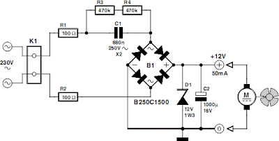
This circuit idea is certainly not new, but when it comes to making a trade-of between using a small, short-circuit proof transformer or a capacitive voltage divider (directly from 230 V mains voltage) as the power supply for a fan, it can come in very handy. If forced cooling is an afterthought and the available options are limited then perhaps there is no other choice. At low currents a capacitive divider requires less space than a small, short-circuit proof transformer. R1 and R2 are added to limit the inrush current into power supply capacitor C2 when switching on. Because the maximum rated operating voltage of resistors on hand is often not known, we choose to have two resistors for the current limit. The same is true for the discharge resistors R3 and R4 for C1. If the circuit is connected to a mains plug then it is not allowed that a dangerous voltage remains on the plug, hence R3 and R4. Circuit diagram: Capacitor C1 determines the maximum current that can be supplied. Above th...