Posts

Showing posts with the label Converter

Simple But Multiple Output DC Converter

Image
This is simple and Low-cost Electronic Circuit Project of Multiple Output DC Converter Circuit Diagram . A DC converter circuit taking one single DC input and converting to parallel multiple DC outputs. Simple But Multiple Output DC Converter Circuit Diagram: Circuit Project Notes : This circuit uses a single DC input (nominally 12 Volt) and converts to four simultaneous output voltages of 9, 6, 5 and 1.5 Volts. The output voltages are controlled by common 78xx series regulators, offering 9, 6 and 5 Volt DC outputs. The 1.5 Volt supply is derived using an LM317 regulator. To reduce power and heat the LM317 is fed from the 5 Volt regulator output. The LM317 output is calculated from: Vo = 1.25 (1 + R1/R2) With R1 200 ohms (use 180 plus 22 ohm in series) this works out to be 1.5 Volt. F2,3,4,5 are the output fuses and are set at 500 mA (0.5 A). If the full 500mA is taken from each output then the DC input supply must be capable of sourcing at least 2 Amp. LED 1 illuminates to show the ci...

10W Power LED Driver using LTC3112 DC Converter

Image
Using the LTC3112 fixed frequency synchronous buck-boost DC DC can be designed a very simple high efficiency, high power led driver electronic project .The unique 4-switch, single inductor architecture of the LTC3112, provides low noise and seamless operation from input voltages above, below or equal to the output voltage.With an input range of 2.7V to 15V, the LTC3112 is well suited for a wide variety of single or multiple cell battery, backup capacitor or wall adapter source applications . Circuit Diagram The LTC3112 features selectable PWM or Burst Mode operation, an easily synchronized oscillator and output disconnect in shutdown. An output current monitor circuit allows the load current to be controlled or measured.Other features of the LTC3112 DC DC converter include : <1 br="br" current="current" short="short" shutdown="shutdown">circuit protection, soft-start, current limit and thermal shutdown. As you can see in the circuit diagram...

Analog to Digital Converter Circuit Diagram

Image
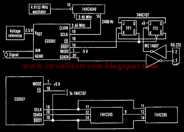
This is a digital Analog to Digital Converter Circuit Diagram. Perhaps the most important consideration of an ADC is its resolution. Because the CS5501 16-bit-delta-sigma analog-to-digital converter lacks a start convert command, it converts continuously, outputting conversion words to its output register every 1024 cycles of its master clock. However, by incorporating a standard dual J-K flip-flop into the circuit, the ADC can be configured to output a single-conversion word only when it is polled.  Analog to Digital Converter Circuit Diagram The CS5501 converter can be operated in its asynchronous communication mode (UART) to transmit one 16-bit conversion word when it is polled over an RS-232 serial line (see figure). A null character (all zeros) is transmitted to the circuit and sets the flip-flop PF2. The CS5501 can then output a single-conversion word, which is transmitted over the RS-232 line as two bytes with start and stop bits. The baud rate can be chosen by selecting t...