Posts

Showing posts with the label converter

DC to DC converter 1 5V to 3V Circuit Diagram

Image
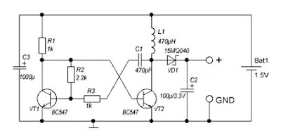
A DC-DC converter 1.5V to 3V Circuit Diagram to reduce the voltage is easy, but the situation becomes more complicated when we have to increase the voltage. This simple scheme generates a voltage 3Vdc from 1.5 VDC, which can be a single stack. We can get good results by modifying an multivibrator using two transistors, the frequency converter is approximately 130 kHz. The inductance value can be calculated experimentally. DC / DC converter 1.5V to 3V Circuit Diagram Schottky diode VD1 can be replaced by any other similar characteristics. For further stabilization of the output voltage can be placed one Zener 3V - 3.3V. This scheme can be used to feed a power LED device, a micro-controller, Arduino, etc. .. List of Components R1, R3: 1K R2: 2K2 C1: 470pF C2: 100uF / 3.3V C3: 1000uF L1: 470UH VD1: 15MQ040 VT1, VT2: BC547

Voltage to pulse Duration Converter

Image
This is a simple circuit diagram of Voltage-to-Pulse Duration Converter. This circuit is used to convert voltage into pulse duration by combining a timer IC and an OP Amp. Accuracies to better than 1% can be obtained with this circuit (a), and the output signals (b) still retain the original frequency, independent of the input voltage. Voltage-to-Pulse Duration Converter Circuit Diagram Voltage levels can be converted to pulse durations by combining an op amp and a timer IC.

DCF77 to USB Converter

Image
I like the handy DCF77 signal. In this project no clock should use it, instead the computers in my home network should be served by a precise time reference. Due to the fact most other interfaces are no longer available on modern computers, it uses the USB to forward the prepared DCF77 signal to the host.

SW Converter for Digital AM Car Radio

Image
SW Converter for Digital AM Car Radio Circuit Diagram This circuit is purposely presented with many loose ends (not literally, of course) to stimulate experimenting with RF circuitry at a small outlay. Looking at the circuit diagram you may recognize a modified version of the SW Converter for AM Radios described elsewhere in this issue. The modifications were necessary to make the circuit compatible with a digital rather than analogue AM car radio. The main difference between digital AM radios and their all-analogue predecessors is that tuning is in 9 kHz (some-times 4.5 kHz steps) in compliance with the international frequency allocation for the band. Obviously, that particular step size, desirable as it may be on MW, is a stumbling block if you want to use a digital AM receiver in combination with a frequency step-up converter for SW, where chaos reigns and there is no fixed step size. The first attempt was to make the crystal oscillator variable by about 5 kHz each way.   SW Co...

Simple 300mA DC to AC converter Circuit Diagram

Image
     This is the Simple 300mA DC to AC converter Circuit Diagram. This circuit was used to provide battery backup to a device that had an AC (output)wall transformer. Due to the quasi sine-wave output and imprecise 60Hz output frequency, some devices might not work pro perly. Peak output is the DC input voltage minus about 20 ohms drop. Use bigger output MOSFETS for more current output.[link]  Simple 300mA DC to AC converter Circuit Diagram

Short Wave Converter Circuit Diagram

Image
This short-wave converter, which doesn’t have a single coil requiring alignment, is intended to enable simple medium-wave receivers to be used to listen to short-wave signals. The converter transforms the 49-m short-wave band to the medium-wave frequency of 1.6 MHz. At the upper end of the medium-wave band, select an unoccupied frequency that you want to use for listening to the converted short-wave signals. Good reception performance can be obtained using a wire antenna with a length of one to two metres. The converter contains a free-running oscillator with a frequency of around 4.4 MHz, which is tuned using two LEDs (which act as variable-capacitance diodes!) and a normal potentiometer. The frequency range is set by adjusting the emitter current using a 1k trimpot. The oscillator frequency depends strongly on the operating point. This is due to the combination of using an audio transistor and the extremely low supply voltage. Under these conditions, the transistor capacitances are r...

12 9 Volt DC to DC Converter BD139

Image
This circuit is a DC voltage output from a small DC input generate large voltage.It ‘s easy and quick to do, and reducing the value of the Z-diode, the circuit can be universally adapted to other output devices of the circuit voltages. The give and all diagrams represent a DC converter with 12V battery 9 volt DC input and output.     12-9 Volt DC to DC Converter Circuit Diagram With the 10V zener diode, as in the diagram, the output voltage is approximately 9.3 volts DC. The supply voltage is used, should always be at least a few volts higher than the Zener voltage. In this example, I have a 12 Volt DC battery to provide regulated 9-volt DC output.

Electronical 6V to 12V Converter Circuit Diagram

Image
      This is the Simple Electronically 6V to 12V Converter Circuit Diagram. This inverter circuit can provide up to 800mA of 12V power from a 6V supply. For example, you could run 12V car accessories in a 6V (British?) car. The circuit is simple, about 75% efficient and quite useful. By changing just a few components, you can also modify it for different voltages.  Electronical 6V to 12V Converter Circuit Diagram Parts R1, R4           2    2.2K 1/4W Resistor    R2, R3           2    4.7K 1/4W Resistor    R5    1            1K 1/4W Resistor    R6    1            1.5K 1/4W Resistor    R7    1            ...

12 V Glow Plug Converter Circuit Diagram

Image
Most small internal-combustion engines commonly used in the model-building world use glow plugs for starting. Unfortunately, glow plugs have an operating voltage of 1.5 V, while fuel pumps, starter motors, chargers and the like generally run on 12 V. This means that a separate battery is always needed to power the glow plug. The standard solution is to use an additional 2-V lead storage battery, with a power diode in series to reduce the voltage by approximately 0.5 V. However, this has the annoying consequence that more than 30 percent of the energy is dissipated in the diode. Naturally, this is far from being efficient.  12-V Glow Plug Converter Circuit Diagram The converter presented here allows glow plugs to be powered from the 12-V storage battery that is usually used for fuelling, charging, starting and so on. A car battery can also be used as a power source. Furthermore, this circuit is con-siderably more efficient than the approach of using a 2-V battery with a series powe...

3 to 12 Volts Converter using LM2700

Image
This Power Supply Electronic Circuit Project a very simple and high efficiency step-up dc dc converter circuit that require few external components can be designed using the LM2700 step-up DC/DC converter with a 3.6A, 80mohms internal switch and pin selectable operating frequency. 3-to-12-Volts Converter Circuit Diagram: With the ability to produce 500mA at 8V from a single Lithium Ion battery, the LM2700 is an ideal part for biasing LCD displays. The LM2700 can be operated at switching frequencies of 600kHz and 1.25MHz allowing for easy filtering and low noise. An external compensation pin gives the user flexibility in setting frequency compensation, which makes possible the use of small, low ESR ceramic capacitors at the output. This circuit can be used for handheld devices and some other portable applications . This step-up DC DC converter will provide a 12 volts DC output voltage from an input voltage range between 2.5 to 4.2volts .

Build a Simple 12v to 9v converter

Image
This little circuit uses a LM317 variable voltage regulator to adjust the input voltage down to +9 volt, or whatever else you need. Just a solid basic circuit without bells and whistles. You can do with a 10uF capacitor for C1 if your battery is close to this circuit. If it is located more than 3 feet increase the value to 100uF or above. Without a coolrib it can easily handle 500mA. If you need more, or the maximum current (1.5A), then a good coolrib is required. Trimmer potent meter R3 will vary the output voltage. Ceramic capacitor C2 improves frequency/transient response. Can be omitted if not needed for your application. If you want extra protection in case the adjust pin is short circuited, add an extra 1N4001 diode over the input and the output. Cathode to input. But normally only used if the output is way over 25V. R1 and R3 determine the output voltage. You can adapt them for your own needs and applications. Use the following formula: (((R1+R3)/R2)+1)*1.25=V-out which...

5V 2A Dc Converter Using LT3980

Image
Using LT3980 manufactured by Linear Technology can be designed a very simple 5 volts dc converter circuit. 5V 2A Dc Converter Circuit Diagram The LT3980 has an adjustable frequency from 100kHz to 2.4MHz and accepts input voltages up to 58V . The transient voltage of the LT3980 is around 80 volts . The maximum output current which can be delivered by the LT3980 monolithic buck switching regulator is around 2 Amps . Main features of the LT3980 monolithic buck switching regulator are : wide input range from 3.6V to 58V , overvoltage lockout protects circuits through 80V transients , 2A Maximum Output Current , low ripple (<15mVP-P) Burst Mode, aAdjustable switching frequency: 100kHz to 2.4MHz ,low shutdown current: IQ < 1μA, thermal protection, Soft-Start Capability .

LT3582 12 DC 5V to 12V DC Converter Circuit Diagram

Image
Using LT3582-12 dual channel DC DC converter integrated circuit, manufactured by Linear Technology, can be designed a very simple step up dc converter. This 5 to 12V c converter electronic project provide both positive and negative outputs required in many biasing applications such as active matrix OLED (organic light-emitting diode)displays as well as CCD (charge coupled device) applications. LT3582-12 DC 5V to 12V DC Converter Circuit Diagram The LT3582 offer an I2C interface that can dynamically program output voltages, power sequencing and output voltage ramps as the application requires. The LT3582’s positive output voltage can be set between 3.2V and 12.775 in 25mV steps, whereas the negative output can be set between -1.2V and -13.95V in 50mV steps. The LT3582-12 is preconfigured with ±12V output, requiring no future programming.

12 Volt to 32 Volt CT converter DC to DC

Image
Kit that can change the normal 12v dc voltage from a car battery, battery bike 12V motor. With the current 7A. so this circuit is very suitable for power car amplifiers and sound systems that use simple 12V battery. Kit converter is also equipped with inputs "SEND" to activate the circuit and also send this interchangeable inputs is connected to the Tape / cd / dvd player of your car. And input "send" is if the non-connected with an output of "send" player car you then connect it to +12 hrs on v from the battery / batteries The series is already in the test kit and has been functioning normally.

1 5V to 5V 12V DC DC Converter with LT1073

Image
 1.5V to 5V/12V DC/DC Converter with LT1073 Circuit Small 1.5V to 5V or 12V DC/DC converter with LT1073 chip. The IC is available in three different versions, depending on output voltage. Two with fixed output voltage of 5V and 12V, and the most interesting that can be adjusted. The adjustment is done through a voltage divider with two resistors, of mass, output and Terminal 8, internally connected to the voltage comparator IC, which is responsible for stabilizing the output voltage.   

Simple 12 16V Converter Circuit Diagram

Image
This is simple 12 -16V converter circuit diagram . Many devices operate from a car`s 12-V electrical system. Some require 12 V; others require some lesser voltage. An automobile battery`s output can vary from 12 to 13.8 V under normal circumstances. The load requirements of the device might vary. This circuit maintains a constant voltage regardless of how those factors change. Simple circuit, A, uses a 7805 voltage regulator.In addition to a constant output, this JC provides overload and short-circuit protection. That unit is a 5-V, 1-A regulator, but when placed in circuit B, it can provide other voltages as well. When the arm of potentiometer R1 is moved toward ground, the output varies from 5 to about 10 V. Simple 12 -16V Converter Circuit Diagram