Posts

Showing posts with the label 220V

250 to 5000 watts PWM DC AC 220V Power Inverter

Image
Build a 250 to 5000 watts PWM DC/AC 220V Power Inverter  This is my schematic design of a Pulse Width Modulator DC/AC inverter using the chip SG3524 . I have built this design and using it as a backup to power up all my house when outages occur. If you like my work and intend to build the circuit don't forget to give me the 5 satrs :D and subscribe to me by clicking on the "follow" button so I know how many people benefit from the design, Thanks Notes: >The schematic circuit design is for a 250 watt output, while the pics are of my 1500 watts inverter that i built, to increase the power of the circuit you have to add more of the Q7 and Q8 transistors in parallel, each pair you add will increase your power by 250 watts, ex: to get 750 watts of power from the inverter you need to add in parallel 2 of Q7 and 2 of Q8 to the original design. >If you increase the power transistors you have to enlarge the T2 transformer to match the new needs, the circuit's ...

Build a 250 to 5000 watts PWM DC AC 220V Power Inverter

Image
Build a 250 to 5000 watts PWM DC/AC 220V Power Inverter  This is my schematic design of a Pulse Width Modulator DC/AC inverter using the chip SG3524 . I have built this design and using it as a backup to power up all my house when outages occur. If you like my work and intend to build the circuit don't forget to give me the 5 satrs :D and subscribe to me by clicking on the "follow" button so I know how many people benefit from the design, Thanks Notes: >The schematic circuit design is for a 250 watt output, while the pics are of my 1500 watts inverter that i built, to increase the power of the circuit you have to add more of the Q7 and Q8 transistors in parallel, each pair you add will increase your power by 250 watts, ex: to get 750 watts of power from the inverter you need to add in parallel 2 of Q7 and 2 of Q8 to the original design. >If you increase the power transistors you have to enlarge the T2 transformer to match the new needs, the c...

110V 220V 500W or more inverter Circuit Diagram

Image
i have constructed this inverter to charge my EV i have 12V DC from solar pannels and i need to recharge my 120V battery pack so i needed an voltage inverter after buying one i have tested it and it blowed in 2 hours so i started building one myself using the ferite transformer and rewired it for my use is very sinple and can be made for every one needs can output any AC voltage with proper wiring i use it only with 110v for my needs but in the diagram i had added another wiring for 110 and 120V as you can see it powers an 200W halogen lamp for testing in test i have used only 2 FETS but they are too hot so i have added another 2 for more power if you use only 250W you can use only 2 with propper cooling if you want more that 500W you need to add another 2 for every 250W of power and use an bigger transformer from my findings this inverter has around 75% performance Be carefull at output you have dangerous voltage Step 1: The built inverter for 250W   A s i said this one gets hotte...

Cheap 12V to 220V Inverter Circuit Project

Image
Cheap 12V to 220V Inverter Circuit Diagram . Even though today’s electrical appliances are increasingly often self-powered, especially the portable ones you carry around when camping or holidaying in summer, you do still sometimes need a source of 230 V AC - and while we’re about it, why not at a frequency close to that of the mains? As long as the power required from such a source remains relatively low - here we’ve chosen 30 VA - it’s very easy to build an inverter with simple, cheap components that many electronics hobbyists may even already have. Though it is possible to build a more powerful circuit, the complexity caused by the very heavy currents to be handled on the low-voltage side leads to circuits that would be out of place in this summer issue. Let’s not forget, for example, that just to get a meager 1 amp at 230 VAC, the battery primary side would have to handle more than 20 ADC!. The circuit diagram of our project is easy to follow. A classic 555 timer chip, identified as...

12V Fan Directly on 220V AC

Image
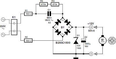
This circuit idea is certainly not new, but when it comes to making a trade-of between using a small, short-circuit proof transformer or a capacitive voltage divider (directly from 230 V mains voltage) as the power supply for a fan, it can come in very handy. If forced cooling is an afterthought and the available options are limited then perhaps there is no other choice. At low currents a capacitive divider requires less space than a small, short-circuit proof transformer. R1 and R2 are added to limit the inrush current into power supply capacitor C2 when switching on. Because the maximum rated operating voltage of resistors on hand is often not known, we choose to have two resistors for the current limit. The same is true for the discharge resistors R3 and R4 for C1. If the circuit is connected to a mains plug then it is not allowed that a dangerous voltage remains on the plug, hence R3 and R4. Circuit diagram: Capacitor C1 determines the maximum current that can be supplied. Above th...

Simple 12V DC to 220V 100W Inverter Circuit Diagram

Image
This is 100W inverter circuit. It uses 4047 IC and IRF540 Mosfet instead of 2N3055 transistor. Power output is 100W from 2-3A transformer. 

110 and 220V AC LED Voltage Indicator

Image
110 and 220V AC LED Voltage Indicator Circuit Diagram. Useful for power lines control, Simple, transformer less circuitry. This circuit, designed on request, has proven to be useful to indicate when the voltage in a power supply line is changing from 120V to 240Vac. It can be used in different circumstances and circuits, mainly when an increase in ac or dc supply voltage needs to be detected. D3 illuminates when the line voltage is approaching 120V and will remain in the on state also at 240V supply. On the other hand, D6 will illuminate only when the line voltage is about 240V and will stay on because the latching action of Q1, Q2 and related components. C1, D1 and D2 provide a low dc voltage in the 4.5V - 6V range in order to allow proper operation of latch circuit and LEDs. Circuit diagram: 110 and 220V AC LED Voltage Indicator Circuit Diagram Parts: R1__________470R 1/2W Resistor R2__________220K 1/4W Resistor R3,R7_______470R 1/4W Resistors R4__________1K 1/4W Resistor R5________...

12V DC to 220V 100W Inverter Circuit Diagram

Image
12V DC to 220V 100W Inverter Circuit Diagram This is 100W inverter circuit. It uses 4047 IC and IRF540 Mosfet instead of 2N3055 transistor. Power output is 100W from 2-3A transformer.

110 and 220V AC LED Voltage Indicator Project

Image
110 and 220V AC LED Voltage Indicator Circuit Diagram. Useful for power lines control, Simple, transformer less circuitry. This circuit, designed on request, has proven to be useful to indicate when the voltage in a power supply line is changing from 120V to 240Vac. It can be used in different circumstances and circuits, mainly when an increase in ac or dc supply voltage needs to be detected. D3 illuminates when the line voltage is approaching 120V and will remain in the on state also at 240V supply. On the other hand, D6 will illuminate only when the line voltage is about 240V and will stay on because the latching action of Q1, Q2 and related components. C1, D1 and D2 provide a low dc voltage in the 4.5V - 6V range in order to allow proper operation of latch circuit and LEDs. 110 and 220V AC LED Voltage Indicator Circuit diagram: 110 and 220V AC LED Voltage Indicator Circuit Diagram Parts: R1__________470R 1/2W Resistor R2__________220K 1/4W Resistor R3,R7_______470R 1/4W Resistors R...

Cheap 12V to 220V Inverter

Image
Even though today’s electrical appliances are increasingly often self-powered, especially the portable ones you carry around when camping or holidaying in summer, you do still sometimes need a source of 230 V AC - and while we’re about it, why not at a frequency close to that of the mains? As long as the power required from such a source remains relatively low - here we’ve chosen 30 VA - it’s very easy to build an inverter with simple, cheap components that many electronics hobbyists may even already have. Though it is possible to build a more powerful circuit, the complexity caused by the very heavy currents to be handled on the low-voltage side leads to circuits that would be out of place in this summer issue. Let’s not forget, for example, that just to get a meager 1 amp at 230 VAC, the battery primary side would have to handle more than 20 ADC!. The circuit diagram of our project is easy to follow. A classic 555 timer chip, identified as IC1, is configured as an astable multivibra...