Posts

Showing posts with the label audio

USB Audio Interface based DAC PCM2902

Image
This is the circuit quality preamplifier with built-in USB DAC for my Leachamp power amplifier. Scheme is PCM2902 datasheet. Circuit includes DAC and ADC, SPDIF input and output of HID and with 3 buttons + MUTE, VOL-and VOL. For playback of high quality needed for external low-drop voltage stabilizer for the DAC. LP2951CM DAC is used, which was readily available in local stores. Output voltage is fixed at about 3.7 V with two resistors. Circuit board is designed with regard to the placement of good land, and the separation of digital and analog ground. These earth are connected in a single point in a USB connector. The PCM2902 data sheet is recommended to connect a low pass filter the DAC output to filter high frequencies above audioband produced by the conversion of oversampling. Digital integrated circuits that includes LPF filter frequency above 100 kHz. In the Notes application filter on the pages of the manufacturer recommends first-order LPF (simple RC) or 2 nd order with amp...

1 W mini audio amplifier circuit

Image
In this circuit requires only three components , namely IC TDA7052 , and 2 capacitor electrolyte. Actually , only with IC we are able to run this amplifier , but the sound less than the maximum. This amplifier circuit requires a minimum voltage of 3 volts and 15 volts maximum. Was 1 Watt power output with 4 Ohm impedance. See this circuit below : Just IC and 3 components we can make the circuit above.

Audio Amplifier Using TDA1519

Image
This audio amplifier circuit is based on the TDA1519 amplifier ic which can be used in audio applications which don’t need high output power .The TDA1519 circuit can deliver 2x6 watts output power . Audio Amplifier Circuit Using TDA1519 TDA1519 is an integrated class-B dual output amplifier in a 9-lead single in-line (SIL) plastic medium power package is primarily developed for car radio applications.This amplifier electronic circuit project needs to be powered from a 14.4 volt DC power supply

50W audio amplifier LM3876 Circuit Diagram

Image
LM3876 is a high performance audio power amplifier IC from National Semiconductors. The LM3876 can deliver 50watts of output power into an 8 ohm loudspeaker. LM3876 has excellent signal to noise ratio and has wide supply voltage range. Other features of LM3876 are output to ground short circuit protection, input mute function, and output over voltage protection, etc. Applications of LM3876 are component stereo, compact stereo, surround systems, self powered speakers, etc. 50W audio amplifier Circuit Diagram The 50 watt audio amplifier  circuit shown below is designed based on the application diagram from the data sheet of LM3876. Some modifications are made on the original circuit for improving the performance. The bipolar electrolytic capacitor C7 is the input DC decoupling capacitor. R4 is the input resistance. R2 & R1 and bipolar electrolytic capacitor C5 forms a feedback circuit. C2, C1 are filter/by-pass capacitors for the positive supply rail. C4 & C3 are the filters...

50W audio amplifier with ICs

Image
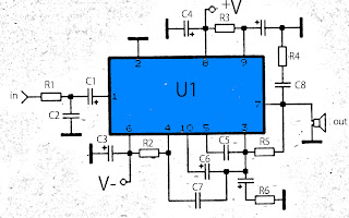
The above amplifier circuit based on IC is STK075G, and another equation that is STK084G, STK085, STK086G. and among ic I mentioned that I recommend using ic high supply voltage and high output power and good quality. You can see every ic datasheet at Alldatasheet.com above. Supply voltage between 20 to 55 Volt DC. Part List R1 = 1K R2 = 100R R3 = 100R R4 = 4.7R R5 = 56K R6 = 47R C1 = 1uF C2 = 470pF C3 = 100uF C4 = 100uF C5 = 1800pF C6 = 1uF C7 = 1800pF C8 = 0.047uF C9 = 100uF U1 = STK075G,  STK084G, STK085, STK086G

35mW audio amplifier

Image
Circuit diagram: 35mW audio amplifier Datasheet for AN7118: Download

20 000 Watt Audio Amplifier Scheme collections

Image
Collection of V ersatile A udioAmplifier N umber 2 Schema 20kW audio amplifier Scheme 2000 Watt Audio Amplifier Scheme 200 Watt Audio Amplifier Scheme 20 Watt Audio Amplifier layout PCB Scheme 2 Watt Audio Amplifier

Reliable 6 Watt Hi Fi Audio Amplifier Using TDA2613

Image
A 6 watt audio amplifier circuit using TDA2613 is shown here. TDA2613 is an integrated Hi-Fi  audio amplifier IC from Philips Semiconductors. The IC is switch ON / switch OFF click proof, short circuit proof, thermally protected and is available in 9 pin single in line plastic package. In the given circuit, TDA2613 is wired to operate from a single supply. Capacitor C4 is the input DC decoupler while capacitors C5, C6 are power supply filters. Input audio is fed to the non inverting input through capacitor C4. Inverting input and Vp/2 pins of the IC are tied together and connected to ground through capacitor C3. Capacitor C2 couples the speaker to the ICs output and the network comprising of capacitor C1 and resistor R1 improves the high frequency stability. . Reliable 6 Watt Hi Fi Audio Amplifier Circuit diagram Notes. Assemble the circuit on good quality PCB. Supply voltage (Vs) can be anything between 15 to 24V DC. Heat sink is necessary for TDA2613. Do not give more than 24V to...

Reliable 6 Watt Hi Fi Audio Amplifier Using TDA2613

Image
A 6 watt audio amplifier circuit using TDA2613 is shown here. TDA2613 is an integrated Hi-Fi  audio amplifier IC from Philips Semiconductors. The IC is switch ON / switch OFF click proof, short circuit proof, thermally protected and is available in 9 pin single in line plastic package. In the given circuit, TDA2613 is wired to operate from a single supply. Capacitor C4 is the input DC decoupler while capacitors C5, C6 are power supply filters. Input audio is fed to the non inverting input through capacitor C4. Inverting input and Vp/2 pins of the IC are tied together and connected to ground through capacitor C3. Capacitor C2 couples the speaker to the ICs output and the network comprising of capacitor C1 and resistor R1 improves the high frequency stability. Reliable 6 Watt Hi Fi Audio Amplifier Circuit diagram Notes. Assemble the circuit on good quality PCB. Supply voltage (Vs) can be anything between 15 to 24V DC. Heat sink is necessary for TDA2613 . Do not give more than 24V ...

Low cost intregated circuit audio power amplifier

Image
This amplifier circuit is very cheap, because not a lot of components that are required, and the voltage or amperage required is also not too large, so the transformer or power supply is also quite cheap. IC which can be used in power amplifier circuit is the KA2201, LM820M, TBA820M, U820. This amplifier output of 2 W and 4 ohm impedance, which can be applied to the speaker with 4W power, on such small speakers in front of a PC. For the required minimum input voltage of 3 volts and a maximum of 16 volts, for the recommended voltage of 12 volts. Parts Resistor R1 = 100K R2 = 120R R3 = 100R R4 = 10R Capacitor C1 = 0.1uF C2 = 100uF C3 = 47uF C4 = 100uF C5 = 470uF C6 = 220pF C7 = 100nF IC U1 = KA2201 , LM820M, TBA820M, U820

Dual 20 Watt audio amplifier

Image
General Description: The AN7190NK and the AN7190NZ are audio power ICs developed for the sound output of car audio (dual 20 W). It is incorporating various protective circuits to protect the IC from destruction by GND-open, short circuit to GND and power supply surge which are the important subject of power IC protection, so the IC will largely contribute to a high reliability design of equipment. Also, it is incorporating a perfect muting circuit which is free from shock noise, so that a shock noise design under the set transient condition can be made easily using together with its standby function.  Circuit Diagram: Dual 20 Watt audio amplifier

LM386N Audio Power Amplifer Amplifier 1x2W

Image
LM386N g eneral description: The LM386 is a power amplifier designed for use in low voltage consumer applications. The gain is internally set to 20 to keep external part count low, but the addition of an external resistor and capacitor between pins 1 and 8 will increase the gain to any value up to 200. The inputs are ground referenced while the output is automatically biased to one half the supply voltage. The quiescent power drain is only 24 milliwatts when operating from a 6 volt supply, making the LM386 ideal for battery operation.  LM386N Audio Amplifier 1x2W LM386N features: Battery operation Minimum external parts Wide supply voltage range: 4V–12V or 5V–18V Low quiescent current drain: 4mA Voltage gains from 20 to 200 Ground referenced input Self-centering output quiescent voltage Low distortion: 0.2% (AV = 20, VS = 6V, RL = 8Ω, PO = 125mW, f = 1kHz) n Available in 8 pin MSOP package LM386N circuit diagram: LM386N Audio Amplifier 1x2W LM386N layout: LM386N pcb layout LM386N p...

7 5 watt audio power amplifier circuit diagram

Image
7.5 watt audio power amplifier circuit diagram

15W Bridge Audio Amplifier Circuit based TDA2002

Image
Build a 15W Bridge Audio Amplifier Circuit based TDA2002. 15W bridge audio amplifier circuit which use 2 pieces of TDA2002. This is audio amplifier for general, work with a single power supply. Use 2A power supply transformer for maximum performance and heatsink should be used to keep the IC from overheating. Build a 15W Bridge Audio Amplifier Circuit based TDA2002 Component part list: R1-5 = 2.7? R2 = 100? R3-4 = 2.2? R6 = 220? R7 = 1M? TR1 = 100K? trimmer C1-9 = 10uF/16V C2-8 = 220uF/16V C3-4-5-7 = 100nF/63V C6=470uF/25V IC1-2=TDA2002 Lsp = 4 – 8?/40W Loundspeaker

1 W mini audio amplifier circuit

Image
In this circuit requires only three components , namely IC TDA7052 , and 2 capacitor electrolyte. Actually , only with IC we are able to run this amplifier , but the sound less than the maximum. This amplifier circuit requires a minimum voltage of 3 volts and 15 volts maximum. Was 1 Watt power output with 4 Ohm impedance. See this circuit below : Just IC and 3 components we can make the circuit above.

Audio Peak Indicator Circuit

Image
The existence of the peak indicator "Audio Peak Indicator" in an audio device is needed. Audio Peak indicator is a simple circuit to detect the peak level of audio signal. Audio Peak indicator circuit is built with duabuah transistor and LED indicator as peak level detection of audio signals. The main function of a series of Audio Peak indicator is to determine the occurrence of the peak level of audio signal that is more than +4 dB, equivalent to 1.25 V rms. If the received audio signal Audio Peak Indicator more than +4 dB was the LEDs in series Peak Audio This indicator will light. Audio Peak indicator circuit is mounted on the output audio system. Audio Peak Indicator Component List: R1 = 10Kohm R2 = 1.2Kohm R3 = 220Kohm R4-5 = 4.7Kohm C1 = 47uF 25V C2 = 2.2uF 25V Q1-2 = BC550C D1 = LED RED We hope to form the reference materials in the manufacture of circuit pernagkat Audio Peak Indicators in the audio readers.

4 x 33Watt power audio amplifier

Image
The HA13155 is four-channel BTL amplifier IC designed for car audio, featuring high output and low distortion, and applicable to digital audio equipment. It provides 33 W output per channel, with a 13.7 V power supply and at Max distortion. Circuit diagram: Datasheet for HA13155: Download

18Watt Audio Amplifier

Image
High Quality very simple unit No need for a preamplifier Circuit diagram : 18Watt Audio Amplifier Circuit Diagram Amplifier parts: P1____22K  Log. Potentiometer (Dual-gang for stereo) R1___1K  1/4W Resistor R2___4K7 1/4W Resistor R3___100R  1/4W Resistor R4___4K7 1/4W Resistor R5___82K  1/4W Resistor R6___10R  1/2W Resistor R7___R22  4W Resistor (wirewound) R8___1K  1/2W Trimmer Cermet (optional) C1___470nF  63V Polyester Capacitor C2,C5___100µF   3V Tantalum bead Capacitors C3,C4___470µF  25V Electrolytic Capacitors C6___100nF  63V Polyester Capacitor D1___1N4148  75V 150mA Diode IC1___TLE2141C  Low noise, high voltage, high slew-rate Op-amp Q1___BC182  50V 100mA NPN Transistor Q2___BC212  50V 100mA PNP Transistor Q3___TIP42A  60V 6A    PNP Transistor Q4___TIP41A  60V 6A    NPN Transistor J1___RCA  audio input socket Power supply : 18Watt Audio Amplifier Power Supply Power supply parts: R9___2K2 1/4W Resistor C7,C8___4700µF 25V Electrolytic Capacitors D2___100V 4...

450W audio power amplifier circuit

Image
Below it is a circuit of power amplifiers with power output of 450 watts mono , amplifiers are also frequently used in the amplifier a high-power amplifier, which used in an event, in the field and the placed closed. Because this amplifier suitable for the woofer, fullrange speaker, and can also be fixed for the subwoofer speaker.  To further strengthen and maximize the amplifier ,its power supply circuit also must be accurate, for electrolytic capacitors in power supply ,voltage capacitors use 80V or more, and a capcity 20000uF upwards, so when the bass amplifier is high , the voltage is not lot of experience dropping. Diode bridge use a minimum of 35A, or adjust the current input voltage. If the power supply has fulfilled the desire, the supply to the power amplifier.