Posts

Showing posts with the label to

How to build Analog Milliamp Meter Used as Voltmeter

Image
A milli Amp analog meter often used along with audio system can be easily converted into a decent volt meter, all that is needed is an understanding of the requirement and the meter. In case a 10V full scale meter is to be designed, then a 10K resistance is to be put in series with the meter coil so that for an applied voltage of 10V a meter can receive 1milliAmp only. The meter itself has an internal resistance and if that is measured properly then in actual practice the resistor to be connected in series shall be having a value of 1000 ohms – IR (internal resistance of the meter). When we measure smaller voltage then this internal resistance of the meter plays a significant role, say for this particular case the internal resistance is 86 ohms, hence, for a I.V. full scale meter the value of the external resistance would be (1000-86) 914 ohms. The milli amp meter can also be used as an Amp meter of higher currents by adding shunt resistances. This is being achieved by simple net...
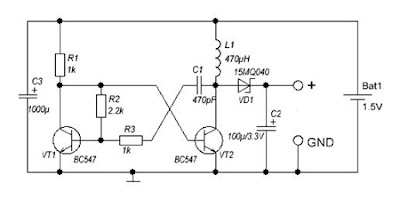
DC to DC converter 1 5V to 3V Circuit Diagram

Image
A DC-DC converter 1.5V to 3V Circuit Diagram to reduce the voltage is easy, but the situation becomes more complicated when we have to increase the voltage. This simple scheme generates a voltage 3Vdc from 1.5 VDC, which can be a single stack. We can get good results by modifying an multivibrator using two transistors, the frequency converter is approximately 130 kHz. The inductance value can be calculated experimentally. DC / DC converter 1.5V to 3V Circuit Diagram Schottky diode VD1 can be replaced by any other similar characteristics. For further stabilization of the output voltage can be placed one Zener 3V - 3.3V. This scheme can be used to feed a power LED device, a micro-controller, Arduino, etc. .. List of Components R1, R3: 1K R2: 2K2 C1: 470pF C2: 100uF / 3.3V C3: 1000uF L1: 470UH VD1: 15MQ040 VT1, VT2: BC547

24V to 12V 400W DC Inverter Circuit

Image
24V to 12V 400W DC Inverter Circuit Diagram 24V to 12V 20A 400W DC to DC Inverter. Does little to change my PV system 12v 24v me the problem arose of what to do with investors who already had 12V. I was looking for a pattern online and found several schemes with linear regulators 20A, this solution although quite simple, due to the huge losses they have is not advisable. Ideally, a converter switched, high-performance. At the end I found nothing I liked and decided to design my own. Circuit characteristics: Output current: 20A at 12V (15A continuous and 30A Momentary), Input voltage: 18 to 30V DC, Output voltage: 5 to 20V, Operating Frequency: 70kHz, Effectiveness: 95%, 400W maximum power, Protections: Above current (30A) in the F1 circuit, D1 and F1 polarity in the circuit.

Voltage to pulse Duration Converter

Image
This is a simple circuit diagram of Voltage-to-Pulse Duration Converter. This circuit is used to convert voltage into pulse duration by combining a timer IC and an OP Amp. Accuracies to better than 1% can be obtained with this circuit (a), and the output signals (b) still retain the original frequency, independent of the input voltage. Voltage-to-Pulse Duration Converter Circuit Diagram Voltage levels can be converted to pulse durations by combining an op amp and a timer IC.

Simple 0V to 50 Volt Variable Regulator

Image
A very simple variable power supply circuit can be made using this electronic circuit diagram .This variable regulator circuit will provide an variable regulated output voltage , between 0 and 50 volts . The CA3140 operational amplifier compares the regulator output to a reference voltage , that depends on the R9 value. Simple 0V to 50 Volt Variable Regulator Circuit Diagram  The output voltage will be nominally twice the voltage between the positive input ( noninverting ) of the CA3140 and ground . The unregulated input voltage must be around 60 volts The output voltage can be set between 0 an 50 volts using R9 potentiometer .The 2N3055 transistors must be mounted on a heatsink , to prevent the overheating of transistors .

DC to AC Inverter with IC CD4047

Image
This DC to AC inverter circuit work based on unstable multi vibrator does. In this circuit, IC CD4047 is chosen as a heart of unstable multivibrator, because this IC type gives a complementary output that has opposite phase to another ( pin 10 and 11 as seen in Figure 1), and has 50 % duty cycle that satisfy to generate a pulse for inverter. DC to AC Inverter with IC CD4047 Circuit Diagram

250 to 5000 watts PWM DC AC 220V Power Inverter

Image
Build a 250 to 5000 watts PWM DC/AC 220V Power Inverter  This is my schematic design of a Pulse Width Modulator DC/AC inverter using the chip SG3524 . I have built this design and using it as a backup to power up all my house when outages occur. If you like my work and intend to build the circuit don't forget to give me the 5 satrs :D and subscribe to me by clicking on the "follow" button so I know how many people benefit from the design, Thanks Notes: >The schematic circuit design is for a 250 watt output, while the pics are of my 1500 watts inverter that i built, to increase the power of the circuit you have to add more of the Q7 and Q8 transistors in parallel, each pair you add will increase your power by 250 watts, ex: to get 750 watts of power from the inverter you need to add in parallel 2 of Q7 and 2 of Q8 to the original design. >If you increase the power transistors you have to enlarge the T2 transformer to match the new needs, the circuit's ...

How to Builed Lamp Fuse Tester

Image
Why a lamp tester or fuse tester? Testing cables, wires, lamps… belongs to a repair job and sometimes this becomes too cumbersome since one has only two hands and too often, one has to hold the part being tester and the two probes of an ordinary continuity tester all at the same time. This fuse and lamp tester enables easy testing of lamps and fuses by using the conductivity of the human body. One of the test probes is connected to the part under test while the other probe is hel dby the normal hand. When the lamp or fuse is working properly, your eyes will glow in the dark! Just kidding :) . When the lamp or fuse is working properly, a small amount of current flows through the hand which is enough to switch the transistors and light the LED.

How To Build Hammonator Organ to Guitar Amp Conversion Circuit Diagram

Image
In the world of electronics, vacuum tubes are almost obsolete. Nearly the last holdout, the cathode ray tube (CRT), is rapidly being replaced by the LCD and other new technologies. Despite this trend, the vacuum tube has seen a big revival in the field of guitar amplifiers, and to a lesser extent, hi-fi amplifiers . Vacuum tubes and related parts have become more readily available in recent years as numerous companies have tapped into this market. The reason for the popularity of tubes in guitar amps involves the nice tones that are produced when tubes are driven to the point of distortion. For some background on this, follow some of the links on The Strat Monger. There are numerous solid state "modeling amps" that try to simulate vacuum tube amps with digital signal processing (DSP) techniques, but in the end, that method is never more than a simulation. It just ain't the same as the real thing. One can spend a large amount of money and time building a tube amp from scra...

Rangemaster Point to Point

Image

DCF77 to USB Converter

Image
I like the handy DCF77 signal. In this project no clock should use it, instead the computers in my home network should be served by a precise time reference. Due to the fact most other interfaces are no longer available on modern computers, it uses the USB to forward the prepared DCF77 signal to the host.

SIMPLE COUNTING CIRCUIT 0 to 99

Image
DIGITAL COUNTING CIRCUIT A simple Digital counting circuit, which will counts from 00 to 99. The counter will incremented by one for each pulse given in the terminal A and B. The pulse can be given by just short circuiting the end points A and B. You can use this circuit for a wide variety of applications such as, for Digital Entry Counter, Speedometer circuit, distance measuring devices etc. CIRCUIT DIAGRAM WORKING PRINCIPLE The 555 timer is wired as an ASTABLE MULTIVIBRATOR, which will generate an output for each pulse given in the terminal A and B. The output is taken from pin 3 and is directly given to the clock input (1) of decoding IC CD4033. CD 4033 is used here as 7 segment Display Driver. The Cout from this IC is given to another CD4033 IC. Which will drive another 7 segment Display. The 7 segment display used here is of Common Cathode type. So the pin 3 is connected to ground. You can increase the number of bits to count in this circuit (99999......) Other useful Links:- INTE...

6 to 12 Volt Power Supply Inverter

Image
This inverter circuit can provide up to 800mA of 12V power from a 6V supply. For example, you could run 12V car accessories in a 6V (British?) car. The circuit is simple, about 75% efficient and quite useful. By changing just a few components, you can also modify it for different voltages. Part List: R1, R4 2.2K 1/4W Resistor R2, R3 4.7K 1/4W Resistor R5 1K 1/4W Resistor R6 1.5K 1/4W Resistor R7 33K 1/4W Resistor R8 10K 1/4W Resistor C1,C2 0.1uF Ceramic Disc Capacitor C3 470uF 25V Electrolytic Capcitor D1 1N914 Diode D2 1N4004 Diode D3 12V 400mW Zener Diode Q1, Q2, Q4 BC547 NPN Transistor Q3 BD679 NPN Transistor L1 See Notes MISC Heatsink For Q3, Binding Posts (For Input/Output), Wire, Board source:LINK

Nicad Battery charger easy to make

Image
Nicad battery charger , this circuit just use transformer not  CT and  3 LEDs lamp. And its very very simple circuit charger . This circuit constant current LEDs to adjust charging current. It uses LEDs that pass a constant  current about 15 mA for an applied voltage range of 2 to 18 Volt. They can be paralleled to give any multiple of 15 mA and they light up when current is flowing. The circuit will charge single cell at 15 , 30 , or 45 mA , or cells in series up to the rated supply voltage limit about 14 Volt. See schematic below : Click to view larger

Simple 300mA DC to AC converter Circuit Diagram

Image
     This is the Simple 300mA DC to AC converter Circuit Diagram. This circuit was used to provide battery backup to a device that had an AC (output)wall transformer. Due to the quasi sine-wave output and imprecise 60Hz output frequency, some devices might not work pro perly. Peak output is the DC input voltage minus about 20 ohms drop. Use bigger output MOSFETS for more current output.[link]  Simple 300mA DC to AC converter Circuit Diagram

Electricity from plant to distribution substation

Image

DC to DC Double Cell Phone Charger Circuit

Image
As we know now a days the main problem is charging of a cell phone when we haven't electricity . And this problem is getting bigger when we have more than one cell phone. So here is the circuit which can be solve our problem for charging more than One cell phone. This circuit of the double DC cell phone charger was successfully tried. The required voltages for the operating of this circuit is 12V DC from a battery source.The transistor T1 which we are using is PnP transistor.The general purpose of this transistor is power application e.g driver stages.The IC1 (7805) is a voltage regulator ic which we are using in this circuit. Parts List R1 = 0.1 Ohms 2 watt, R2 = 2 Ohms 2 Watt R3 = 3 Ohms 1 watt C1 = 100uF/25V C2 = 0.1 disc T1 = BD140 D1 = 1N5408 IC1 = 7805

How To Connect Two Computers Using Modems

Image
Have you ever connected two PCs together via modems using a twisted pair cable and nothing happened? That’s because the modems are expecting a phone line with all the signals and voltages supplied by the local telephone exchange. This circuit simulates the DC power and signal isolation but not the "dial tone" or the "ring signal". It suffices to connect two PCs together to communicate and exchange files using HyperTerminal. The circuit is self-explanatory and needs only one power supply for both modem lines. Although 50V DC is the usual exchange line voltage, this circuit should operate down to 20V. A 600O line transformer (eg. Jaycar cat. MM-1900) provides signal isolation, while the resistors provide current limiting and keep the lines as balanced as possible. Circuit diagram: How To Connect Two PCs Using Modems Circuit Diagram When using this set-up with HyperTerminal, you should not select a Windows modem driver in the "Connect To" dialog. Instead, con...

How to Reuse Old Cell Battery for LED lighting

Image
Normally cell batteries have a shelf life of 2 to 5 years under normal use . After that time we have to replace them . Nowadays there replacement batteries which are cheap, but these batteries last for much less cost only months. An easy solution is to use batteries in a circuit that requires less current , we can use them for lighting LEDs .  How to Reuse Old Cell Battery for LED lighting 

Build a 250 to 5000 watts PWM DC AC 220V Power Inverter

Image
Build a 250 to 5000 watts PWM DC/AC 220V Power Inverter  This is my schematic design of a Pulse Width Modulator DC/AC inverter using the chip SG3524 . I have built this design and using it as a backup to power up all my house when outages occur. If you like my work and intend to build the circuit don't forget to give me the 5 satrs :D and subscribe to me by clicking on the "follow" button so I know how many people benefit from the design, Thanks Notes: >The schematic circuit design is for a 250 watt output, while the pics are of my 1500 watts inverter that i built, to increase the power of the circuit you have to add more of the Q7 and Q8 transistors in parallel, each pair you add will increase your power by 250 watts, ex: to get 750 watts of power from the inverter you need to add in parallel 2 of Q7 and 2 of Q8 to the original design. >If you increase the power transistors you have to enlarge the T2 transformer to match the new needs, the c...