Posts

Showing posts with the label amplifier

TDA2003 Car amplifier

Image
This is a very popular series of amplifiers audio users who require maximum aduio results and of course with a relatively cheap price. This circuit requires a minimum voltage and maximum 9 Volt and 30 Volt. This amplifier circuit using ic TDA2003, which is used in car audio power, because of making these amplifiers can easily be made on each speaker of the amplifier. By using ic and component quality is very good circuit used separately. The circuit can be seen below.   Technical information: Supply voltage = 12V Output             = 10W 

50W audio amplifier LM3876 Circuit Diagram

Image
LM3876 is a high performance audio power amplifier IC from National Semiconductors. The LM3876 can deliver 50watts of output power into an 8 ohm loudspeaker. LM3876 has excellent signal to noise ratio and has wide supply voltage range. Other features of LM3876 are output to ground short circuit protection, input mute function, and output over voltage protection, etc. Applications of LM3876 are component stereo, compact stereo, surround systems, self powered speakers, etc. 50W audio amplifier Circuit Diagram The 50 watt audio amplifier  circuit shown below is designed based on the application diagram from the data sheet of LM3876. Some modifications are made on the original circuit for improving the performance. The bipolar electrolytic capacitor C7 is the input DC decoupling capacitor. R4 is the input resistance. R2 & R1 and bipolar electrolytic capacitor C5 forms a feedback circuit. C2, C1 are filter/by-pass capacitors for the positive supply rail. C4 & C3 are the filters...

50W audio amplifier with ICs

Image
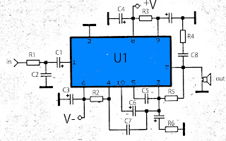
The above amplifier circuit based on IC is STK075G, and another equation that is STK084G, STK085, STK086G. and among ic I mentioned that I recommend using ic high supply voltage and high output power and good quality. You can see every ic datasheet at Alldatasheet.com above. Supply voltage between 20 to 55 Volt DC. Part List R1 = 1K R2 = 100R R3 = 100R R4 = 4.7R R5 = 56K R6 = 47R C1 = 1uF C2 = 470pF C3 = 100uF C4 = 100uF C5 = 1800pF C6 = 1uF C7 = 1800pF C8 = 0.047uF C9 = 100uF U1 = STK075G,  STK084G, STK085, STK086G

Low cost intregated circuit audio power amplifier

Image
This amplifier circuit is very cheap, because not a lot of components that are required, and the voltage or amperage required is also not too large, so the transformer or power supply is also quite cheap. IC which can be used in power amplifier circuit is the KA2201, LM820M, TBA820M, U820. This amplifier output of 2 W and 4 ohm impedance, which can be applied to the speaker with 4W power, on such small speakers in front of a PC. For the required minimum input voltage of 3 volts and a maximum of 16 volts, for the recommended voltage of 12 volts. Parts Resistor R1 = 100K R2 = 120R R3 = 100R R4 = 10R Capacitor C1 = 0.1uF C2 = 100uF C3 = 47uF C4 = 100uF C5 = 470uF C6 = 220pF C7 = 100nF IC U1 = KA2201 , LM820M, TBA820M, U820

2 X 1 8 Watt stereo low power amplifier circuit

Image
This is Low power amplifier , based on IC TDA2824 product of Philips. Maximum output is about 2 X 1,8 Watt , these include low  output amplifier type. Minimum required voltage 3 Volts and maximum voltage of 18 volts DC. Specification : Supply Voltage : 3 - 18 Volts Power Output   : 2 x 1,3 Watts RL impedance  : 4 Ohms Frequency responses : 30Hz -18kHz Quiescent current : 6 mA                

Stereo 9 Volt power amplifier circuit

Image
Here I will explain about the necessary voltage and power amplifier output. The voltage should have at least approximately 9Volt 30Volt voltage and maximum voltage on the DC current. For maximum output of 2 X 2Watt with impedance 8-16 ohm. Because this amplifier circuit using ic and ic is used have the equation, so that if used different ic, then the required output voltage and also differ depending ic respectively. Part List : Resistor R1 = 1M R2 = 1M R3 = 1K R4 = 1K R5 = 100K R6 = 100K R7 = 1R R8 = 1R Capacitor C1 = 1uF C2 = 220uF C3 = 1uF C4 = 100uF C5 = 5uF C6 = 5uF C7 = 0.1uF C8 = 220uF C9 = 220uF C10 = 0.1uF IC U1 = ULN2274B , ULN2277 , ULN2278B

Low Noise operational amplifier

Image
Low noise balanced input is can also call for the circuit schematic above , because it has a very small noise output and balanced on each input . The noise output is only  117.0 dBu, its very small maybe even not at all out noise. The schematic based on IC5532 , to maintain ic remain good and avoid damage, you should install heatsink in every IC. If the circuit is finished and ready to use, then connect circuit in final befor going out to other components . Because this circuit is also suitable as a buffer amplifier.

18 W stereo amplifier circuit

Image
TDA1009 circuit amplifier , this circuit is stereo amplifier and simple schematic .Minimum voltage require 9V and maximum voltage 24V. To avoid damaged IC please use supply voltage 12 volt and must be filtering voltage. Power output 2 X 18 W with impedance 4 Ohm.See circuit schematic and troubleshooting amplifier : Click to view larger  If circuit not working ,possible cause is on : Supply voltage. Components damaged , such as IC , resistor ,and Capacitor. Installation components inverted. Broken line PCB. Input not connected. Or input grounding. Output Not connected. Speakers damaged.

4 x 33Watt power audio amplifier

Image
The HA13155 is four-channel BTL amplifier IC designed for car audio, featuring high output and low distortion, and applicable to digital audio equipment. It provides 33 W output per channel, with a 13.7 V power supply and at Max distortion. Circuit diagram: Datasheet for HA13155: Download

RF amplifier protection

Image
RF amplifier protection I have developed the protection circuit for the EB104 amplifier I am working on, after I finally had some time to design and test a few models. The main requirements have been: - protection in case of high temperature; - protection in case of high SWR; - protection in case of wrong output filter selection; - simple design (i’m a fan of the whole K.I.S.S. rule of thought), able to work in strong electromagnetic fields, reliable, inexpensive. Because i will be using the same directional coupler i have used in the SWR meter (the one made on PCB) wich is directly influenced by the signal frequency, and because i want full HF coverage, i cannot just measure the reflected signal and make a circuit cut the amplifier when it goes over a limit; on 28Mhz the coupler generates roughly 4 times more voltage that let’s say in 7Mhz. So a system that compares direct and reflected signal and triggers when the latter is percentually too high was needed, therefore an operational a...

100W BTL TDA2030 amplifier circuit

Image
TDA2030 amplifier circuit using the BTL system has a 100W output power and voltage of +15 V,-15V 0 . Amplifier circuit you can see below. TDA2030 100W amplifier circuit Click image above to view larger.

3V 35mW dual power amplifier

Image
3V / 35mW dual power amplifier