Posts

Showing posts with the label On

Alternating ON OFF Control

Image
Use this circuit instead of a standard on-off switch. Switching is very gentle. Connect unused input pins to an appropriate logic level. Unused output pins *MUST* be left open!. First 'push' switches ON, another 'push' switches OFF. You can use 1/4 watt resistors if they are metal-film type. Any proper substitute will work for Q1, including the european TUN's. For C2, if you find the relay acts not fast enough, leave it out or change to a ceramic cap between 10 and 100nF. Parts List All resistors are 1/2 Watt and 5% tolerance. R1 = 10K R2 = 100K R3 = 10K C1 = 0.1µF, Ceramic C2 = 1µF/16V, Electrolytic D1= 1N4001 Q1 = 2N4401 (ECG123AP, NTE123AP, etc.) IC1 = 4069, CMOS, Hex Inverter (14069), or equivalent S1 = Momentary on-switch Source by : Streampowers

Print On Polymer Multiplies Solar Output

Image
PORTLAND, Ore. — Scientists have demonstrated a doubling of the number of electrons produced by carbon-based photovoltaic polymer potentially doubling the efficiency of any solar cell. The process called “singlet fission” produces “identical twin” electrons from a single photon, instead of the normal one, dramatically boosting the theoretical maximum output of solar cells. Instead of loosing energy to heat, an extra electron is produced by the process of applying a polymer solution to an existing solar cell. “One of the challenges in improving the efficiency of solar cells is that a portion of the absorbed light energy is lost as heat,” lead scientist at Brookhaven National Labs, Matt Sfeir, told EE Times. “In singlet fission, one absorbed unit of light results in two units of electricity via a multiplication process rather than resulting in one unit of electricity and heat as would occur in a conventional cell.” [ ]

Big Muff or others Tone Stack Daughter Board Add On

Image

Unique amplifier circuit schmeatic based on IC TDA7255

Image
This circuit equipped with 2 switches that are useful for loudness and filtering, on SW1 as the loudness , SW2 as a filter. It also equipped with direct  adjust of sound on Potentiometer 10k , but only useful as a master volume. Minimum Voltage  : 8 volts Maximum Voltage : 18 volts Maximum Power   : 2 X 13 Watt stereo Impedance Power  : 4 Ohms

Final Nikon Coolpix S800c Runs on Android 2 3 Gingerbread

Image
Normally, when we talk about an Android-powered system, we would venture into the realm of smartphones and tablets, and very rarely (if ever) into the world of digital cameras. The line is about to be blurred this day, as the Nikon Coolpix S800c was just announced to come with a copy of the Android operating system – Android 2.3 Gingerbread, to be exact. Yes sir, how does this digital camera shape up in the face of a mobile operating system running in the background? Well, we shall have to take a closer look at its machinations and inner workings right after the jump, shall we not ? For starters, with Android running on the Nikon Coolpix S800c, you might actually feel that you are using a smartphone at times – until you realize that you are unable to make any phone calls or receive text messages. Good thing it has Wi-Fi connectivity built in though, as it would not be much of an Android device if there were not Internet connectivity to make it interactive. Setting up the camera for Int...

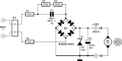
12V Fan Directly on 220V AC

Image
This circuit idea is certainly not new, but when it comes to making a trade-of between using a small, short-circuit proof transformer or a capacitive voltage divider (directly from 230 V mains voltage) as the power supply for a fan, it can come in very handy. If forced cooling is an afterthought and the available options are limited then perhaps there is no other choice. At low currents a capacitive divider requires less space than a small, short-circuit proof transformer. R1 and R2 are added to limit the inrush current into power supply capacitor C2 when switching on. Because the maximum rated operating voltage of resistors on hand is often not known, we choose to have two resistors for the current limit. The same is true for the discharge resistors R3 and R4 for C1. If the circuit is connected to a mains plug then it is not allowed that a dangerous voltage remains on the plug, hence R3 and R4. Circuit diagram: Capacitor C1 determines the maximum current that can be supplied. Above th...

On off Infrared Remote Control Circuit

Image
Description  Most homes today have at least a few infrared remote controls, whether they be for the television, the video recorder, the stereo, etc. Despite that fact, who among us has not cursed the light that remained lit after we just sat down in a comfortable chair to watch a good film? This project proposes to solve that problem thanks to its original approach. In fact, it is for a common on/off switch for infrared remote controls, but what differentiates it from the commercial products is the fact that it is capable of working with any remote control. Therefore, the first one you find allows you to turn off the light and enjoy your movie in the best possible conditions. The infrared receiver part of our project is entrusted to an integrated receiver (Sony SBX 1620-52) which has the advantage of costing less than the components required to make the same function. After being inverted by T1, the pulses delivered by this receiver trigger IC2a, which is nothing other than a D fli...

Color Lights on USB

Image
This project is a remake of an old discolights pod. Original 24V 5W bulbs are changed to 230V 40W with E14 thread. Original driver board has non-typical signal input. This driver is based on the FT245RL chip, a USB-LPT converter – so you can use it with PC applications such as discolitez. Low voltage part is supplied directly from the USB so there is no need to to use any transformer… Device uses a MOC3041 optotriac and a BT136 triac in a standard application to drive bulbs. Note if you want to use stronger bulbs, like 100W or more, you need to use some little radiators to cool down the triacs. There are 4 channels, 3 are used for bulbs and 4th is used as an extra 230V output – in this case for a mini strobe. You can find 4 goldpins on board, these are a 4 extra output channels – so you can expand device to another optotriacs and triacs to use 4 more 230V devices. To your own safety, use a proper fuse, and remember that device works on a 230V potential. You can use it with 110V devices...