Posts

Showing posts with the label LED

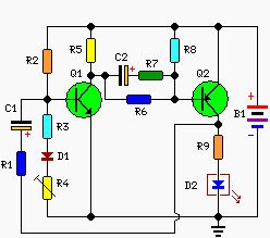
Flashing LED Battery Status Indicator Circuit
Image
A Battery-status Indicator circuit can be useful, mainly to monitor portable Test-gear instruments and similar devices. LED D1 flashes to attire the user's attention, signaling that the circuit is running, so it will not be left on by mistake. The circuit generates about two LED flashes per second, but the mean current drawing will be about 200µA. Transistors Q1 and Q2 are wired as an uncommon complementary astable multivibrator: both are off 99% of the time, saturating only when the LED illuminates, thus contributing to keep very low current consumption. Circuit operation: The circuit will work with battery supply voltages in the 5 - 12V range and the LED flashing can be stopped at the desired battery voltage (comprised in the 4.8 - 9V value) by adjusting Trimmer R4. This range can be modified by changing R3 and/or R4 value slightly. When the battery voltage approaches the exhausting value, the LED flashing frequency will fall suddenly to alert the user. Obviously, when the batter...

WS2811 chip black PCB 32led per meter individually addressable LED digit

Image
This is 5V drive IC WS2801 magic RGB Dream Color Series Programmable LED Flexible Strip Lights, 32LEDs per meter, 160LEDs per reel, Full color LED strip light, Digital led flexible strip, Can perform various effects by full color led controller. The WS2801 IC now only has 4 pins, durable and easy for installation. This simpler layout and can be controlled separately to each one lamp, every LED is cuttable. Low working voltage, DC5v, ensure safety in wet condition. The transparent of silicon glue and epoxy resin glue can make the light transmittance reach at least 90%,the bare board can make it up to 100%. our company specialize in designing drive control scheme and developing new product  for led decorative lighting and LED lighting industry, providing all-dimensional solutions.We mainly engaged in designing and selling the led lighting drive IC,LED lighting constant current driving IC,LED lighting control system. Good service,comprehensive pre-sale and after-sale service, also pro...

6V Ultra Bright LED Chaser Circuit Diagram

Image
This is a spectacular but completely useless project. It lights Ultra-Bright LEDs in a sequence and each LED flashes brightly very briefly. The LEDs light-up going around and around since they are mounted in a circle (on a CD), then they pause before chasing again. The very brief flash of each LED (15ms) and the pauses (1 second) reduce the average current so the battery should last a long time.   For user convenience, this project has a stepper speed control and a brightness control. At slower speeds and/or reduced brightness, the battery’s life is extended considerably. At full brightness, the LEDs flash extremely brightly. More than one of this project grouped together occasionally synchronize, lighting the whole room for a moment. Operation At maximum speed, the LEDs don’t appear to flash, instead they appear to move from one lighted one to the next, around and around. They rotate completely for 4 rotations in two seconds, and then turn off for a one second pause then rep...

Build a 16 LED Chaser Circuit Diagram

Image
This 16 LED Chaser Circuit Diagram is a double direction flash. Similar to Digital Ping- Pong 1, there is a movement of a lit dot, up and down along the LED's length. 16 LED Chaser Circuit Diagram When the D16 lit the situation changes and there is a reverse movement. Lit D15-14 ……D16, is lit making circles when the circuit is under power. The IC1 is an unstable flip- flop supplying with stable frequency pulses (the frequency can be changed by TR1, adjusting the velocity of the LED's up and down). This frequency supplies the IC3 (which is a 4-Bit UP and DOWN counter) through 2 gates A-B of the IC2. The output counter supplies the IC4 that is the driver of the LED's. The parts C- D of The IC2, make a R-S flip- flop, that changes situation, when the edge LED's D1 and D16 lit. We have an electronic limit for the situation change. In proportion the shape we make with the LED's, we can have the proportionate optional result, making various effects. Part List R1= 100Kohm...

Solar Panel Based Charger And Small LED Lamp

Image
You can save on your electricity bills by switching to alternative sources of power. The photovoltaic module or solar panel described here is capable of delivering a power of 5 watts. At full sunlight, the solar panel outputs 16.5V. It can deliver a current of 300-350 mA. Using it you can charge three types of batteries: lead acid, Ni-Cd and Li-ion. The lead-acid batteries are commonly used in emergency lamps and UPS. The working of the circuit is simple. The output of the solar panel is fed via diode 1N5402 (D1), which acts as a polarity guard and protects the solar panel. An ammeter is connected in series between diode D1 and fuse to measure the current flowing during charging of the batteries. As shown in Fig. 1, we have used an analogue multimeter in 500mA range. Diode D2 is used for protection against reverse polarity in case of wrong connection of the lead-acid battery. Charger circuit diagram: Solar Panel Based Charger Circuit Diagram When you connect wrong polarity, the fuse ...

LED Flasher With One Transistor Circuit Project

Image
This is a unique flasher circuit employing a single driver transistor that takes its flash-rate from a flashing LED. The flasher within the photo is 3mm. An ordinary LED won't work. The flash rate can not be altered by the brightness of the high-bright white LED will be adjusted by altering the 1k resistor across the 100u electrolytic to 4k7 or 10k. The 1k resistor discharges the 100u in order that when the transistor activates, the charging current into the 100u illuminates the white LED. If a 10k discharge resistor is used, the 100u isn't absolutely discharged and therefore the LED doesn't flash as bright. All the components within the photo are within the same places as within the circuit diagram to make it simple to envision how the components are connected. The circuit uses a flashing LED to flash a super-bright 20,000mcd white LED

How to Reuse Old Cell Battery for LED lighting

Image
Normally cell batteries have a shelf life of 2 to 5 years under normal use . After that time we have to replace them . Nowadays there replacement batteries which are cheap, but these batteries last for much less cost only months. An easy solution is to use batteries in a circuit that requires less current , we can use them for lighting LEDs .  How to Reuse Old Cell Battery for LED lighting 

Constant Current LED Drive

Image
Most LED driver circuits use a series resistor to control the current through the LED. For applications needing a few LEDs, this is optimal. However, for applications needing many LEDs, this becomes extravagantly inefficient and it is tempting to keep the voltage drop across the resistor as small as possible. That leads to poor control of the current. ICs such as the MM5450 and its relatives and the A6275 and its relatives provide constant current outputs so that the current through the LEDs is well controlled even though the voltage drop across the circuit doing the control is acceptably small. However, the difficulty with these circuits is that because they contain many constant current drivers crowded into a relatively small package, unless the supply voltage is small, they become too hot and can destroy themselves. Circuit diagram: Constant Current LED Drive Circuit Diagram This problem is not easy to solve. The solution is to maintain a small voltage across each constant current s...

How to build a Simple LED Volt Meter

Image
This is a Simple LED Volt meter to Monitor the charge level in Lead Acid Battery or Tubular battery. The terminal voltage of the battery is indicated through a four level LED indicators. The nominal terminal voltage of a Lead Acid battery is 13.8 volts and that of a Tubular battery is 14.8 volts when fully charged.  Simple LED Volt Meter Circuit Diagram The LED voltmeter uses four Zener diodes to light the LEDs at the precise breakdown voltage of the Zener diodes. Usually the Zener diode requires 1.6 volts in excess than its prescribed value to reach the breakdown threshold level. When the battery holds 13.6 volts or more, all the Zener breakdown and all LEDs light up. When the battery is discharged below 10.6 volts, all the LEDs remain dark. So depending on the terminal voltage of the battery, LEDs light up one by one or turns off.

Build a Logic Level Signals Dim 48V LED Driver

Image
The main source of power in a telecommunications system is -48 V. This source’s negative polarity and its large magnitude with respect to ground pose a challenge when designers want to use low-power ICs in the telecom system’s application circuits. Fortunately, the emergence of high-voltage ICs with operating voltages of 75 V and higher has enabled the use of simple biasing techniques in designing circuits for -48-V systems. The technique described here provides a dimming control for an LED. The circuit uses a 65-V hysteretically controlled LED driver (MAX16822A) with its ground pin connected to -48 V and its power input connected to the system ground (Fig. 1). For proper dimming, therefore, the circuit’s logic-level control signal (at Control) must be level-shifted down to –48 V and applied to the DIM input. The high-voltage pnp transistor (CMPT5551) (80 V/500 mA) enables a simple solution to that problem. Logic-Level Signals Dim -48V LED Driver Circuit Diagram The transistor circuit ...

LED Mini Audio Analyzer circuit Diagram

Image
This analyst is, a sensitive instrument, in the frequency changes   and width of a acoustic signal. Thus the brightness of LED that turns on each moment of is proportional signal width, while the colour of proportionally frequency. Mini Audio Analyzer Circuit Diagram The circuit input sensitivity is regulated with R2, in order that in powerful signals they turn on the red LED , in the middle the yellow LED and in the low green LED . The display unit, is constituted by 3 lines of 10 LED the every, what is checked by a counter decoder (IC2). Two gates ICa-b, function as the IC2, with the R6 regulate the frequency. When does not exist signal in the input, then no one LED does not turn on. As soon as it will be applied signal, then the LED will begin to blink depending on the rythm and the intensity of signal. Can experiment with the prices of resistances R4, R5, so that you find the value that suits in like your. Initially it can they are placed trimmer 1KO, in the place o...

8 Stage LED VU Meter

Image
The circuit below uses two quad voltage comparators (LM339) to illuminate a series of 8 LEDs indicating volume level. Each of the 8 comparators is biased at increasing voltages set by the voltage divider so that the lower right LED comes on first when the input is about 400 millivolts or about 22 milliwatts peak in an 8 ohm system. Circuit diagram : 8 Stage LED VU Meter Circuit Diagram The divider voltages are set so that each LED represents about twice the power level as the one before so the scale extends from 22 milliwatts to about 2.5 watts when all LEDs are lit. The sensitivity can be decreased with the input control to read higher levels. I have not built or tested this circuit, so please let me know if you have problems getting it working. The power levels should be as follows: 1 LED = 22mW 2 LEDs = 42mW 3 LEDs = 90mW 4 LEDs = 175mW 5 LEDs = 320mW 6 LEDs = 650mW 7 LEDs = 1.2 Watts 8 LEDs = 2.5 watts

10W Power LED Driver using LTC3112 DC Converter

Image
Using the LTC3112 fixed frequency synchronous buck-boost DC DC can be designed a very simple high efficiency, high power led driver electronic project .The unique 4-switch, single inductor architecture of the LTC3112, provides low noise and seamless operation from input voltages above, below or equal to the output voltage.With an input range of 2.7V to 15V, the LTC3112 is well suited for a wide variety of single or multiple cell battery, backup capacitor or wall adapter source applications . Circuit Diagram The LTC3112 features selectable PWM or Burst Mode operation, an easily synchronized oscillator and output disconnect in shutdown. An output current monitor circuit allows the load current to be controlled or measured.Other features of the LTC3112 DC DC converter include : <1 br="br" current="current" short="short" shutdown="shutdown">circuit protection, soft-start, current limit and thermal shutdown. As you can see in the circuit diagram...

Dimmable White LED Lamp

Image
Nowadays you can buy white LEDs, which emit quite a bit of light. They are so bright that you shouldn’t look directly at them. They are still expensive, but that is bound to change. You can make a very good solid-state pocket torch using a few of these white LEDs.  Dimmable White LED Lamp  Circuit Diagram  The 12V DC input voltage is routed through the 1A fuse and the on/off switch. The 1N4001 diode acts as a crowbar device. If reverse polarity is applied, the fuse will blow and the rest of the circuitry will be protected. Power is sent to the LM2941CT voltage regulator IC. The regulator is wired to produce a voltage range from 5.5V (dim) to 8.3V (bright).  The 4.7K resistor across the 1K brightness adjustment potentiometer produces a non-linear brightness adjustment to compensate for the eye's logarithmic brightness perception response. The LEDs are organized in six series groups of three with a 24 ohm current limiting resistor on each group. This arrangement limits...

Regulated Dual 3 Watt White LED Lamp

Image
This project involves constructing an energy efficient dual 3 Watt white LED array that runs on 12VDC at 700mA. The lamp is useful for indoor indirect room lighting. The light that is produced does not flicker and has a regulated brightness from 11V to the maximum operating voltage. The Avago 3W white LEDs are rated at 3 watts (nominal). Never stare directly at this lamp when it is running at full operating power, it is dangerously bright. Specifications: Nominal operating voltage: 12V DC Nominal operating current: 700 mA Maximum operating voltage: 16V DC Power consumption at 12.0V: 8.4W Minimum voltage for regulated light: 11V DC Leds produce light down to: 6V DC White LED voltage: 3.7V DC each White LED input power: 2.59 W each Voltage across regulator when current becomes regulated: 3.3V DC Theory: The lamp is wired as a current loop which includes the power supply, the LED series string and the 700 mA current regulator circuit. The LM317 and 1.8 ohm 5 Watt resistor act as a current...

LED TV

Image
LED TV INTRODUCTION LED TV (Light-emitting diode television) is a term used by Samsung electronics and other consumer electronics companies to describe its line of LCD (liquid crystal display) TVs that use LED backlighting. The term LED TV is disputed and the complaint is that the display is not composed of 100% LEDs and so should not be called LED TV. LEDs in their current form are much too large to be individual pixels on a conventional television. The use of a true LED display is therefore reserved for much larger screens in sports grounds and other commercial locations. LED-backlit LCD TVs do differ from conventional LCD TVs in some important areas: • They can produce a very bright image with greater contrast and deeper blacks compared with LCD TVs. • With Edge-LED lighting they can be extremely slim. Current models on the market are just over 1 inch thick. • They consume much more power. About 40% less compared with an LCD TV of a similar size. • They can offer a wider colour gamu...

Led Flasher with the LM3909 IC streampowers

Image
Introduction The LM3909 is an integrated circuit (IC) which will flash a light-emitting diode (LED). Using only two extra components and a battery, the circuit is cheap and has a very low current drain from a 1.5 V cell. The circuit can be used as a novelty flasher, an indicator for a dummy alarm bell box, or it could be attached to a torch so that it could be found easily in the dark! The simple circuit Led Flasher with the LM3909 IC Diagram Assembly The circuit can be built on a small piece of Veroboard (the piece shown in Figure 2 measures 15 holes by 10 strips). Using such a board, follow these instructions. 1. Depending on how far away you want the LED from the circuit board, solder a length of insulated wire to each lead of the LED. Use different colours of insulation – say, red and black, connecting the red lead to the anode (a) lead (the longer one) of the LED, and the black one to the cathode (k). Figure 2 shows these leads. 2. Cut the copper tracks as shown i...

LED Voltmeter Circuit Diagram

Image
This is a simple LED Voltmeter Circuit Diagram. Four µ741 op-amps are used here to measure the voltage ranging from 3V to 12V DC. The voltage measured is displayed on eight LEDs. The inverting inputs (pin 2) of IC1 through IC4 are supplied with regulated 12V DC through voltage dividers R1 through R4. So the inverting input of each op-amp forms the reference voltage. The non-inverting inputs (pin 3) of the op-amps are tied together and connected to the input terminals. The voltage to be meaured is fed to these input terminals. When the input voltage exceeds the reference voltage of any of the op-amps, its output goes high, making the corresponding LED s to glow. This circuit is designed to measure 3V, 6V, 9V and 12V DC. For instance, when the input voltage is 3V, LED 7 and LED8 glow. When the input voltage is 12V, all the LED s glow. Note. You can use a quad device such as LM324 instead of µ741 IC s.  LED Voltmeter Circuit Diagram

LED 230 V Flasher Circuit diagram

Image
This circuit operates with 230v.you can use this circuit to decorate your parties.I think this will be a wonderful circuit to you all.This circuit was taken from my old circuit book called 100 circuit book.Here DIAC ER 900 and Triac BTW 11-400. 230 V Flasher Circuit diagram Note: Be careful when you deal with 230V Build this circuit on a PCB Use only mentioned values.  Sourced By: Freecircuitsdiagram4u

UP DOWN FADING LED CIRCUIT USING NE555

Image