Posts

Showing posts with the label Indicator

Flashing LED Battery Status Indicator Circuit

Image
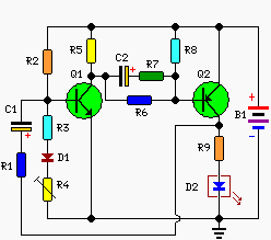
A Battery-status Indicator circuit can be useful, mainly to monitor portable Test-gear instruments and similar devices. LED D1 flashes to attire the user's attention, signaling that the circuit is running, so it will not be left on by mistake. The circuit generates about two LED flashes per second, but the mean current drawing will be about 200µA. Transistors Q1 and Q2 are wired as an uncommon complementary astable multivibrator: both are off 99% of the time, saturating only when the LED illuminates, thus contributing to keep very low current consumption. Circuit operation: The circuit will work with battery supply voltages in the 5 - 12V range and the LED flashing can be stopped at the desired battery voltage (comprised in the 4.8 - 9V value) by adjusting Trimmer R4. This range can be modified by changing R3 and/or R4 value slightly. When the battery voltage approaches the exhausting value, the LED flashing frequency will fall suddenly to alert the user. Obviously, when the batter...

Simple Transmission Indicator Circuit Diagram

Image
This is the Simple Transmission Indicator Circuit Diagram. This circuit the push-to-talk button is closed the light will go on. The antenna samples the output RF from the transmitter. That signal is then rectified (detected) by germanium diode Dl, and used to charge capacitor C2. Simple Transmission Indicator Circuit Diagram The dc output is used to trigger a small silicon-controlled rectifier (SCR1), which permits the current to flow through the small pilot lamp. For lower-power applications, such as CB radio, the antenna will have to be close-coupled to the antenna.

Maximum Minimum Voltage Indicator

Image
This circuit indicates which of three voltages in the range from about about -4V to about +4V - at A, B and C - is the highest by lighting one of three indicator LEDs. Alternatively, it can be wired to indicate the lowest of three voltages or to indicate both the highest and lowest voltages. Op amps IC1a, IC1b & IC1c are wired as comparators, while the three indicator LEDs and their series 1kO current limiting resistors are strung across the op amp outputs to implement the appropriate logic functions. Maximum Minimum Voltage Indicator Circuit diagram:  Maximum Minimum Voltage Indicator Circuit Diagram For example, LED A will light only when pin 8 of IC1c is low (ie, A greater B) and pin 7 of IC1b is high (ie, A greater C). Similarly, LED B will light only when pin 8 of IC1c is high (ie, B greater A) and pin 1 of IC1a is low (ie, B greater C). LED C works in similar fashion if the voltage at C is the highest. Note that if all the LEDs and their parallel 1N4148 diodes are revers...

Indicator Consumption AC Load Circuit Diagram

Image
This is Indicator consumption AC Load Circuit Diagram . Some types of electronic equipment does not show that in fact they are consuming energy when they are plugged into an outlet. This pilot light is not required if the unit consumes less than 10 watts according to international standards. But if you turn off the equipment, will be contributing with nature and your pocket, reducing the bill. One way to detect the AC power being consumed, independent of the load is connected in series with a diode AC power supply. In this circuit 6A diodes have been used which can withstand a peak current of 200A is not repeated. Indicator consumption AC Load Circuit Diagram The voltage between the diodes serves as the voltage supply for the LED and circuit. To increase the sensitivity of the circuit, we used a voltage doubler consisting of C1, D7, D8 and C2 is used to double the voltage of D1-D6. Another advantage of this scheme is that both reduce by half waves of alternating current. Must use Schot...

Network Voltage Indicator

Image
Using this schematic can be made a network voltage indicator electronic circuit. If the input voltage is present across the network, the optocoupler transistor is open, T1 is blocked and controlled rectifier, Th1, is in a state of conduction. Since both terminals of the piezoelectric buzzer is at the same potential, buzzer is off. If voltage disappears, the transistor T1 enters the conduction and thus makes the terminal of buzzer to be put on the ground (maintains thyristor conduction state).  Network Voltage Indicator Circuit diagram: In this situation, there is a sufficiently large potential difference across the buzzer and D5's to determine that these two elements to indicate AC power loss, both audible and visual. By pressing the reset button current is interrupted by Th1, so thyristor enter in blocking state and the other terminal of the buzzer is connected to ground.

Digital Mains Voltage Indicator

Image
Continuous monitoring of the mains voltage is required in many ap-plications such as manual volt-age stabilisers and motor pumps. An ana-logue voltmeter, though cheap, has many disadvantages as it has moving parts and is sensitive to vibrations. The solidstate voltmeter circuit described here indicates the mains voltage with a resolution that is comparable to that of a general-pur-pose analogue voltmeter. The status of the mains voltage is available in the form of an LED bar graph. Presets VR1 through VR16 are used to set the DC voltages corresponding to the 16 voltage levels over the 50-250V range as marked on LED1 through LED16, respectively, in the figure. The LED bar graph is multiplexed from the bottom to the top with the help of ICs CD4067B (16-channel multiplexer) and CD4029B (counter). The counter clocked by NE555 timer-based astable multivibrator generates 4-bit binary ad-dress for multiplexer-demultiplexer pair of CD4067B and CD4514B.  Digital Mains Voltage Indicator Circ...

Supply Voltage Indicator

Image
Supply Voltage Indicator Circuit Diagram. A novel supply voltage monitor which uses a LED to show the status of a power supply.This simple and slightly odd circuit can clearly show the level of the supply voltage (in a larger device): as long as the indicator has good 12 volts at its input, LED1 gives steady, uninterrupted (for the naked eye) yellow light. If the input voltage falls below 11 V, LED1 will start to blink and the blinking will just get slower and slower if the voltage drops further - giving very clear and intuitive representation of the supply's status. The blinking will stop and LED1 will finally go out at a little below 9 volts. On the other hand, if the input voltage rises to 13 V, LED2 will start to glow, getting at almost full power at 14 V. The characteristic voltages can be adjusted primarily by adjusting the values of R1 and R4. The base-emitter diode of T2 basically just stands in for a zener diode. Supply Voltage Indicator Circuit Diagram Supply Voltage Ind...

Simple Rf Output Indicator Circuit Diagram

Image
This is the Simple Rf Output Indicator Circuit Diagram. In this electronic circuit A simple RF detector circuit using a visual indicator can be useful for an RF output indicator, etc. This circuit was used for a transmitter ON indicator. Simple Rf Output Indicator Circuit Diagram 

Low Cost Low State Car Battery Indicator

Image
Here is very simple low-cost electronic circuit project of low state car battery indicator circuit. This electronic circuit diagram designed using few common electronic parts. This low state battery electronic project can be used to monitor car battery voltage. Low-Cost Low State Car Battery Indicator Circuit Diagram: The warning light LED indicates when battery indicates battery voltage falls bellow level set by 10k potentiometer, if the battery is defective or needs charging if cranking drops battery voltage bellow preset safe limit. This circuit project is very simple so it not requires some other explanation.

Fastest Finger First Indicator Circuit Project

Image
Fastest Finger First Indicator Circuit Diagram . Quiz-type game shows are increasingly becoming popular on tale vision these days. In such games, fastest finger first indicators (FFFIs) are used to test the player’s reaction time. The player’s designated number is dis played with an audio alarm when the player presses his entry button. The circuit presented here determines as to which of the four contestants first pressed the button and locks out the remaining three entries. Simultaneously, an audio alarm and the correct decimal number display of the corresponding contestant are activated.  Fastest Finger First Indicator Circuit Diagram   When a contestant presses his switch, the corresponding output of latch IC2 (7475) changes its logic state from 1 to 0. The combinational circuitry comprising dual 4-input NAND gates of IC3 (7420) locks out subsequent entries by producing the appropriate latch-disable signal. Priority encoder IC4 (74147) encodes the active-low input conditio...

Simple Fuse Monitor Indicator

Image
The idea for this project may have come to me in a flash of inspiration, and its a very simple way to check if a fuse has blown without removing it from its holder. Simple Fuse Monitor Indicator Circuit Diagram :   The simplicity of this circuit uses just two components, but with just one resistor and an LED this circuit gives visual indication of when a fuse has blown. LED1 is normally off, being "short circuited " by the fuse, F1. Should the inevitable "big-bang" happen in your workshop then LED1 will illuminate and led you know all about it! Please note that the LED will only illumininatet under fault conditions, i.e. with a short circuit or shunt on the load. In this case the current is reduced to a safe level by R1.

110 and 220V AC LED Voltage Indicator

Image
110 and 220V AC LED Voltage Indicator Circuit Diagram. Useful for power lines control, Simple, transformer less circuitry. This circuit, designed on request, has proven to be useful to indicate when the voltage in a power supply line is changing from 120V to 240Vac. It can be used in different circumstances and circuits, mainly when an increase in ac or dc supply voltage needs to be detected. D3 illuminates when the line voltage is approaching 120V and will remain in the on state also at 240V supply. On the other hand, D6 will illuminate only when the line voltage is about 240V and will stay on because the latching action of Q1, Q2 and related components. C1, D1 and D2 provide a low dc voltage in the 4.5V - 6V range in order to allow proper operation of latch circuit and LEDs. Circuit diagram: 110 and 220V AC LED Voltage Indicator Circuit Diagram Parts: R1__________470R 1/2W Resistor R2__________220K 1/4W Resistor R3,R7_______470R 1/4W Resistors R4__________1K 1/4W Resistor R5________...

Equipment Indicator Using Two LED

Image
This simple circuit aims to provide an indication of an appliance if it is ON or OFF with the use of green and red LEDs. BC337 – a small signal NPN Silicon AF medium power transistor used for general purpose switching and amplifying applications with features such as TO-18 manufactured package, suited for AF driver stages and low power output stages, and divided into three group types. Single Pole Single Throw (SPST) – a single on-off switch where the two terminals are either connected together of not connected to anything The indication produced by the LEDs could mean that the red LED will illustrate that the equipment is turned ON while the green LED will illuminate upon turning OFF the same appliance. It could also be the other way around since green normally signifies that there is life on an equipment. This is applicable with any appliance that is powered and operated by AC mains which can be 230 V or 115 Vac. A suitable switch SW1 made of single pole single throw type will be cap...

Network Voltage Indicator Circuit Diagram

Image
Using this schematic is created a network voltage indicator electronic circuit. If the input voltage is gift across the network, the optocoupler transistor is open, T1 is blocked and controlled rectifier, Th1, is in a very state of conduction. Since each terminals of the piezoelectric buzzer is at identical potential, buzzer is off. If voltage disappears, the transistor T1 enters the conduction and therefore makes the terminal of buzzer to be placed on the bottom (maintains thyristor conduction state). during this state of affairs, there's a sufficiently giant potential distinction across the buzzer and D5's to see that these 2 components to point AC power loss, each audible and visual. By pressing the reset button current is interrupted by Th1, therefore thyristor enter in blocking state and therefore the different terminal of the buzzer is connected to ground. http://streampowers.blogspot.com/2012/07/sp-network-voltage-indicator.html 

Audio Peak Indicator Circuit

Image
The existence of the peak indicator "Audio Peak Indicator" in an audio device is needed. Audio Peak indicator is a simple circuit to detect the peak level of audio signal. Audio Peak indicator circuit is built with duabuah transistor and LED indicator as peak level detection of audio signals. The main function of a series of Audio Peak indicator is to determine the occurrence of the peak level of audio signal that is more than +4 dB, equivalent to 1.25 V rms. If the received audio signal Audio Peak Indicator more than +4 dB was the LEDs in series Peak Audio This indicator will light. Audio Peak indicator circuit is mounted on the output audio system. Audio Peak Indicator Component List: R1 = 10Kohm R2 = 1.2Kohm R3 = 220Kohm R4-5 = 4.7Kohm C1 = 47uF 25V C2 = 2.2uF 25V Q1-2 = BC550C D1 = LED RED We hope to form the reference materials in the manufacture of circuit pernagkat Audio Peak Indicators in the audio readers.

Indicator Consumption AC Load Circuit Diagram

Image
This is Indicator consumption AC Load Circuit Diagram . Some types of electronic equipment does not show that in fact they are consuming energy when they are plugged into an outlet. This pilot light is not required if the unit consumes less than 10 watts according to international standards. But if you turn off the equipment, will be contributing with nature and your pocket, reducing the bill. One way to detect the AC power being consumed, independent of the load is connected in series with a diode AC power supply. In this circuit 6A diodes have been used which can withstand a peak current of 200A is not repeated. Indicator consumption AC Load Circuit Diagram The voltage between the diodes serves as the voltage supply for the LED and circuit. To increase the sensitivity of the circuit, we used a voltage doubler consisting of C1, D7, D8 and C2 is used to double the voltage of D1-D6. Another advantage of this scheme is that both reduce by half waves of alternating current. Must use Schot...

Stereo Peak Indicator

Image
The circuit diagram shows a low-cost, fast responding, peak holding, audio level indicator. The sensitivity is determined by preset P1, which (sort of) DC-biases the input of Schmitt-trigger gate IC1a to a level close to the switching threshold. When the negative peaks of the audio signal cause the output of the first Schmitt trigger gate to go high, the capacitor on the input of the second Schmitt trigger gate rapidly charges via diode D1. The charge can only disappear via the 1-Mohm resistor, R2, so a fast attack, slow decay is the result. In this way, even the fastest peaks will be caught and indicated by LED D2. Four NAND gates in a single 4093 package make a stereo version. A multiturn quality trimpot will ensure easy adjustment and stable function over time. Circuit Diagram : Stereo Peak Indicator Circuit Diagram The circuit is based on a standard CMOS IC and will work from any supply voltage between 5 and 15 V. Author : F. Jensen - Copyright : Elektor

110 and 220V AC LED Voltage Indicator Project

Image
110 and 220V AC LED Voltage Indicator Circuit Diagram. Useful for power lines control, Simple, transformer less circuitry. This circuit, designed on request, has proven to be useful to indicate when the voltage in a power supply line is changing from 120V to 240Vac. It can be used in different circumstances and circuits, mainly when an increase in ac or dc supply voltage needs to be detected. D3 illuminates when the line voltage is approaching 120V and will remain in the on state also at 240V supply. On the other hand, D6 will illuminate only when the line voltage is about 240V and will stay on because the latching action of Q1, Q2 and related components. C1, D1 and D2 provide a low dc voltage in the 4.5V - 6V range in order to allow proper operation of latch circuit and LEDs. 110 and 220V AC LED Voltage Indicator Circuit diagram: 110 and 220V AC LED Voltage Indicator Circuit Diagram Parts: R1__________470R 1/2W Resistor R2__________220K 1/4W Resistor R3,R7_______470R 1/4W Resistors R...

Accu Indicator Circuit Diagram

Image
The battery indicator can monitor the voltage on the car battery. The indicator has four LEDs that indicate the voltage. The more LEDs, the higher the voltage. The last LED is a blinking LED. This lights up when the battery voltage exceeds the limit of about 15 V.  This is a sign that something is wrong with the alternator or voltage regulator. The other LEDs light up respectively at 9 V (D5: bad battery), 11 V (D7: battery doubtful) and 13 V (D9: battery ok).Build the the activation points above. Circuit and verify If the measured values ​​are much different from the above, try other Zener diodes. Zeners 300 mW are sufficient for the circuit. Simple Accu Indicator Circuit Diagram Parts List      D1, D2, D3, D4 = 1N4002      D5 = LED green      D7 = LED yellow      D9 = LED red      D11 = LED flashing      Zener diode D6 = 4.7 V/300 mW      D8 ...