Posts

Showing posts with the label 1

BOSS DS 1 DS1 DS 2 DS2

Image

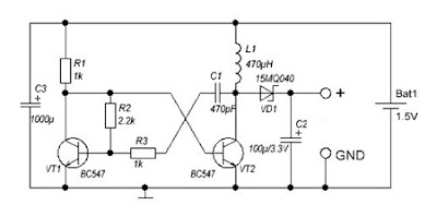
DC to DC converter 1 5V to 3V Circuit Diagram

Image
A DC-DC converter 1.5V to 3V Circuit Diagram to reduce the voltage is easy, but the situation becomes more complicated when we have to increase the voltage. This simple scheme generates a voltage 3Vdc from 1.5 VDC, which can be a single stack. We can get good results by modifying an multivibrator using two transistors, the frequency converter is approximately 130 kHz. The inductance value can be calculated experimentally. DC / DC converter 1.5V to 3V Circuit Diagram Schottky diode VD1 can be replaced by any other similar characteristics. For further stabilization of the output voltage can be placed one Zener 3V - 3.3V. This scheme can be used to feed a power LED device, a micro-controller, Arduino, etc. .. List of Components R1, R3: 1K R2: 2K2 C1: 470pF C2: 100uF / 3.3V C3: 1000uF L1: 470UH VD1: 15MQ040 VT1, VT2: BC547

1 Watt Tiny Audio Amplifier Using LM386

Image
Tiny Audio Amplifier Using LM386 Specifications The Tiny Audio Amplifier kit is a good choice for battery operation. It is based on LM386 IC. Power supply - 6 - 12 VDC Output power - 1 W, 8 Ohm The quiescent power drain is only 24 mW when operating from 6 VDC Self-centering output quiescent voltage Onboard PRESET to adjust volume Terminal pins for connecting power supply, audio signal and speaker Power-On LED indicator ON/OFF PCB mounted slide switch for power supply Four mounting holes of 3.2 mm each PCB dimensions 44 mm x 44 mm Schematic Inputs - Outputs configuration    Parts List  PCB

1 W mini audio amplifier circuit

Image
In this circuit requires only three components , namely IC TDA7052 , and 2 capacitor electrolyte. Actually , only with IC we are able to run this amplifier , but the sound less than the maximum. This amplifier circuit requires a minimum voltage of 3 volts and 15 volts maximum. Was 1 Watt power output with 4 Ohm impedance. See this circuit below : Just IC and 3 components we can make the circuit above.

TL071 MOSFET Audio Amplifier 1 x 70w

Image
TL071 MOSFET Audio Amplifier    g eneral description:       This simple mosfet power audio amplifier circuit, with TL071 and 2 mosfets (IRF9530, IRF530) power amplifiers can deliver up to 45W on 8 ohm. This schematic is based on Siliconix application and is based on variations of voltage on the 2 resistors serial inserted on the voltage supplier of the operational amplifier driver.  The mosfet transistors must be mounted on a heatsink at least 1K/W.   Amplifier efficiency is 70%, distortions at cut frequency were at most 0.2% at 20Hz on 8 ohm and 10W. With a power supply of +/- 30V the mosfet audio amplifier can deliver 45W on 8 ohm and 70w on 4 ohm. Remember that this audio amplifier is not protected on short circuits so every time you switch on check to see if the speaker is connected. MOSFET Audio Amplifier    Circuit diagram:

Build a 1 3 32 V 5A Power Supply w Short Circuit Protection by LM338

Image
Project Description This is a very easy to build power supply that is based on LM338 5A adjustable voltage regulator. I am using the supply for a long time, have no problem yet. Only current adjust is missing but I overcome this situation by using an LCD panel ampermeter.  There is no PCB for the circuit. I took a 3x16 copper plate and strip the unused areas by a knife. If you want you can use analog meters instead of LCD panels.    Notes Use thick wires for connections.When connecting the LM338 to the heatsink use thermal paste. Use external supplies for LCD panels. They can be 9V batteries. The panels I use draws 1mA current and the batteries last sufficiently long time. If you have small transformers which can supply regulated 9V, you can use them. You need separate transformers for each panel!The transformer should be 100 Watt but if you don't need high current you can try transformers that you already have. (I can draw 6A from 100Watt transformer.)If you have ...

5 1 Channel Home Theater Onkyo HT S3500

Image
In support of slight- to way-sized accommodation, you can't pass away ancient times the well-balanced and inexpensive HT-S3500 in plays package. Newly equipped with Onkyo's WRAT (eclectic Range Amplifier skill), the AVR and six-amp synchronize desire disrupt and delight with audio performance you would expect from a added expensive organization. The package is trouble-free to set up due away from home of the box, appreciation to the intuitive HDMI®-overlaid On-Screen put on view and fortification-mountable speakers.  Four HDMI inputs provide connectivity designed for BD players and gaming consoles, and near's an Audio Return Channel to dispatch tube audio through the receiver. Plug your iPod®/iPhone® into the front-panel USB and benefit from transparent, powerful sound with an inbuilt optimizer enhancing the quality of compressed digital song. The AVR decodes Dolby® TrueHD and DTS-HD Master Audio™, and is keen pro 3D games and movies. absolute for replacing an aging procedu...

Nmos Power Amplifier Series Part 1

Image
Nmos200 - TO220 A compact power amplifier module capable of up to 200 watts into a 4 ohm load depending on power supply and the output mosfets used.  The module is limited to rails of +/- 50v max.  The amplifier can be built using either TO220 or TO247 style Mosfets. Schematic Diagram Nmos200-TO220 Layout Nmos200-TO220 Nmos200 - TO247  Nmos200 - TO247 Stereo Schematic Diagram Nmos200-TO247 Layout Nmos200-TO247

Mantis 9 1 CNC Mill

Image
The Mantis 9.1 design is a radical departure from version 8 and earlier. Most notably, the part count has been almost halved! The current design has 13 parts, all of which can be made with a handsaw and a drill press. Also, I’ve traded away my alignment free exactly-constrained design for extra stiffness. Several unsuccessful attempts to eradicate the last of the slop in the Z axis on version 8 lead me back to the world of over-constrained parallel rods. My previous attempts at an over-constrained design (versions 1-5) all failed because I was unable to make the rods sufficiently parallel to avoid jamming. What to do? [ ]

Audio signal processing 1 W × 2 channel

Image
Overview: AN12942B is an one-chip IC for the stereo speakers which can output 1 W by 8 Ω, headphone amplifiers, line amplifiers, and electronic volumes. The AGC circuit is built-in to prevent the resonance or the vibration by the speaker’s energy and the clipping distortion what is  called "broken up sound".  Also the AN12942B is built-in power saving on/off function automatically detecting input signal to save the power of speaker  amplifier. Circuit Diagram: Audio signal processing

2 X 1 8 Watt stereo low power amplifier circuit

Image
This is Low power amplifier , based on IC TDA2824 product of Philips. Maximum output is about 2 X 1,8 Watt , these include low  output amplifier type. Minimum required voltage 3 Volts and maximum voltage of 18 volts DC. Specification : Supply Voltage : 3 - 18 Volts Power Output   : 2 x 1,3 Watts RL impedance  : 4 Ohms Frequency responses : 30Hz -18kHz Quiescent current : 6 mA                

The Voyager 1 Got to Deep Space on Less Memory Than Your iPhone 5

Image
  Whereas it's traveled 11.6 billion miles to interstellar space, Voyager 1's software isn't as high-tech as you may believe. In detail, it has less than 40 KB of recollection. To put that in viewpoint, your 16 GB iPhone 5 has about 240,000 times the recollection of a Voyager spacecraft. NASA developed Voyager in the 1970s in a pre-computer era when scientists had to rely solely on pencil, paper, chalkboards and their own mathematical abilities. While that appears unimaginable in a time when we contain decades' worth of computational power in our pouches, Voyager 1 is one of NASA's most thriving missions, and project researcher Edward Stone states he wouldn't have changed a thing. "It's astonishing it's continued as long as it has," pebble notifies Mashable. "I don't know how we could have done things much better than they were finished. I mean things do wear out, and we've had to swap to some of our backup schemes, but luckily we ...

1 2 30V 1 5A Variable Regulated Power supply Project

Image
This is a project of 1.2-30V/1.5A Variable Regulated Power supply, This is simple 1.2-30V/1.5A variable regulated power supply circuit diagram The 110V-AC coming from the powercord is fed to the transformer TR1 via the on-off switch and the 500mA fuse. The 30vac output (approximately) from the transformer is presented to the BR1, the bridge-rectifier, and here rectified from AC (Alternating Current) to DC (Direct Current). If you don't want to spend the money for a Bridge Rectifier, you can easily use four general purpose 1N4004 diodes. The pulsating DC output is filtered via the 2200µF capacitor (to make it more manageable for the regulator) and fed to 'IN'-put of the adjustable LM317 regulator (IC1). The output of this regulator is your adjustable voltage of 1.2 to 30volts varied via the 'Adj' pin and the 5K potmeter P1. The large value of C1 makes for a good, low ripple output voltage.  1.2-30V/1.5A Variable Regulated Power supply Circuit Diagram Why exactly 1.2V...

1 3 32 V 5A Power Supply w Short Circuit Protection by LM338

Image
Project Description This is a very easy to build power supply that is based on LM338 5A adjustable voltage regulator. I am using the supply for a long time, have no problem yet. Only current adjust is missing but I overcome this situation by using an LCD panel ampermeter.  There is no PCB for the circuit. I took a 3x16 copper plate and strip the unused areas by a knife. If you want you can use analog meters instead of LCD panels.    Notes Use thick wires for connections.When connecting the LM338 to the heatsink use thermal paste. Use external supplies for LCD panels. They can be 9V batteries. The panels I use draws 1mA current and the batteries last sufficiently long time. If you have small transformers which can supply regulated 9V, you can use them. You need separate transformers for each panel!The transformer should be 100 Watt but if you don't need high current you can try transformers that you already have. (I can draw 6A from 100Watt transformer.)If you have...

3 in 1 Flash Light

Image
Want to avoid the problem of carrying three different flashlights to perform a test? Why don’t you try integrating Ultra Violet, Infra Red and visible light together in one flashlight? Read on to know more about this. The multi-tasking flashlight is basically composed of a metallic case, a switch, cables and connections, four 9V batteries and three different LED heads that provide the desired light beam. For the construction of this flashlight, LedEngin’s LZ4-40 is recommended. This comes with a very wide wavelength that includes infra red and ultra violet light. Distinct visible light color temperature can also be found The first step is to build the body of the flashlight, using an aluminum tube. Next come the drilling and cutting for switches and covers. Once the body is finished, the work on the constant current driver should be completed, adding the proper terminals for the batteries and the base for the LED heads.  Once all the power source wiring is completed and insulated w...

VOX Octa Voice I 1

Image

IR Remote Control Extender Mark 1

Image
Description This circuit is used to relay signals from an Infra Red remote control in one room to an IR controlled appliance in another room. Forward I have seen these devices advertised in magazines, they sell for around £40-£50 and use radio to transmit between receiver and transmitter. This version costs under £5 to make and uses a cable connection between receiver and transmitter. For example, if you have a bedroom TV set that is wired to the video or satellite in another room, then you can change channels on the remote satellite receiver using this circuit. The idea is that you take your remote control with you, aim at the IR remote control extender which is in the same room, and this will relay the IR signal and control the remote appliance for you. The circuit is displayed below: Parts List: 1 SFH2030 Photodiode 1 TIL38 IR emitting diode 1 5mm Red LED 2 4.7M 1/4W resistors 1 1k 1/4W resistor 1 2.2k 1/4W resistor 1 27ohm 1/2W resistor 1 BC337 transistor 1 CA3140 MOSFET opamp The ...

1 W mini audio amplifier circuit

Image
In this circuit requires only three components , namely IC TDA7052 , and 2 capacitor electrolyte. Actually , only with IC we are able to run this amplifier , but the sound less than the maximum. This amplifier circuit requires a minimum voltage of 3 volts and 15 volts maximum. Was 1 Watt power output with 4 Ohm impedance. See this circuit below : Just IC and 3 components we can make the circuit above.

1 2 36V 5A Adjustable Power Supply with LM317

Image
Build a 1.2-36V 5A Adjustable Power Supply circuit diagram with LM317 . This circuit is a simple power supply circuit. 1.2 - 36V adjustable bench power supply with 5A of output current. Max input voltage is 37V and output is adjustable via potentiometer between 1.2 up to 36 volts. TIP147 PNP darlington transistor boosts the current of LM317 from 100mA to 5A. LM317 is the most useful and inexpensive adjustable regulator and for this circuit you can also use LM317 L that can give 100mA, that's enough for transistor bias.   1.2-36V 5A Adjustable Power Supply Circuit Diagram  D1 and D2 are protection diodes because when you turn the circuit off the output capacitors are discharging and can damage the transistor or regulator. 100nf capacitors are in parallel with electrolytic capacitors to remove high frequency noise because large value electrolytic have large ESR and ESL and can't remove high frequency noise.

1 W Home Stereo Amplifier Circuits Diagram

Image
This is a one watt home stereo amplifier module project using the KA2209 IC from Samsung, which is equivalent to the TDA2822. It operates from 3-12V DC & will work from a battery since the dormant current drain is low. It requires no heat sink for normal use. The input & output are both ground referenced. Maximum output will be obtained with a 12V power supply & 8 ohm speaker, however it is suitable for driving headphones from a supply as low as 3V. The Specifications of the home stereo amplifier : D.C. input : 3 – 12 V at 200 – 500 mA max Idle current : approx. 10 mA Power output : > 1 Watt max. 4-8 ohms, 12V DC Freq. Resp. : approx. 40 Hz to 200 kHz, 8 ohm, G=10 THD : < 1 % @ 750 mW, 4-8 ohm, 12V Gain : approx. x10 (20 dB) OR x100 (40dB) S/N ratio : > 80 dB, G = 20 dB Sensitivity : < 300 mV, G = 20 dB Input Impedance : approx. 10 k ohm Description   The gain is adjustable from ten to 100, i.e. twenty to 40 dB. Start with feedback resistors R1 and R3 of 1k ...