Posts

Showing posts from May, 2017

High Efficiency LED Torch

Image
THE high forward voltage of l.e.d.s is a challenge for efficient battery use. In the circuit shown in Fig.1a, a 74HC14 inverter is used to “double” the voltage of a 6V rechargeable ex-mobile-phone battery and drive a string of three 5mm l.e.d.s. The oscillator around IC1a and IC1b generates a square wave at about 2·8kHz, and its output is buffered by IC1c and IC1d used in parallel to maximise current to the doubler. Booster Using a 6V supply and with 1N4148 diodes in the rectifier, which comprises D1 and D2 plus capacitors C2 to C4, results in a rectified voltage of 9·6V having a 12mA output capability for a 24mA supply current – an electrical efficiency of over 80%. Using a 6·3V battery the output voltage is 10V and the available current increases to 16mA. If Schottky diodes are used for D1 and D2, there is an increase in voltage of 100mV, resulting in a 20% increase in available current, to 19mA (6·3V supply), at similar efficiency, and a much brighter light. Using these diodes there

12V Fan Directly on 220V AC

Image
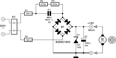
This circuit idea is certainly not new, but when it comes to making a trade-of between using a small, short-circuit proof transformer or a capacitive voltage divider (directly from 230 V mains voltage) as the power supply for a fan, it can come in very handy. If forced cooling is an afterthought and the available options are limited then perhaps there is no other choice. At low currents a capacitive divider requires less space than a small, short-circuit proof transformer. R1 and R2 are added to limit the inrush current into power supply capacitor C2 when switching on. Because the maximum rated operating voltage of resistors on hand is often not known, we choose to have two resistors for the current limit. The same is true for the discharge resistors R3 and R4 for C1. If the circuit is connected to a mains plug then it is not allowed that a dangerous voltage remains on the plug, hence R3 and R4. Circuit diagram: Capacitor C1 determines the maximum current that can be supplied. Above th

Battery Level Monitor Circuit

Image
Battery Level Monitor Circuit This simple circuit can monitor the charging process in 12 Volt Lead Acid battery or Tubular battery. The status of LED indicates whether the battery is accepting charge or not. It also indicates the full charge condition. Battery Level Monitor Circuit Diagram The circuit can be incorporated in any battery charger like 6 volt, 9 volt, 12 volt etc. The only change needed is replacement of the Zener ZD with appropriate value. That is for 6 volt charger , use 6.1 volt Zener and for 9 volt charger it should be 9.1 volt Zener. The circuit is based on the switching of two NPN transistors (BC547) to drive the corresponding LED. Zener diode ZD is connected to the base of T1 so as to switch on T1 when the Zener conducts. This happens only when the battery voltage is above 12 volts. Green LED lights when the battery voltage is normal or battery attains full charge. Resistor R1 and Preset VR adjust the base bias of T1 for smooth switching. When T1 conducts, base of T

Digital Bike Tachometer Circuit Diagram

Image
This is the simple tachometer for bikes uses 2 reed switches to urge the speed data of the bicycle. The reed switches are put in close to the rim of the wheel where permanent magnets pass by. The permanent magnets are connected to the wheelspokes and activate the reed switches everytime they pass by it. The speed is digitally displayed. The tachometer circuit works in step with this principle; the pulses created by the reed contacts are counted inside an explicit time interval. The ensuing count is then displayed and represents the speed of the bike. 2 4026 ICs are used to count the pulses, decode the counter and management 2 7-segment LED show. RS flip-flops U3 and U4 perform as anti-bounce. Electronic bicycle SP tachometer circuit diagram The pulses arrive at the counter’s input through gate U7. The measuring amount is set by monostable multivibrator U5/U6 and might be adjusted through potentiometer P1 so the tacho are often calibrated. The circuit U1/U2 resets the counters. Since ba

Storage and Handling of Tools

Image
Storage and Handling of Tools Tools are of many forms and sizes and, when stored and handled carelessly, can easily cause accidents. To avoid this, storage facilities must be provided in the electrical workshop. Tools may be stored in: a. tool box b. tool kit, c. tool rack. For easy identification, simple sketches of the tools may be painted in the storage facilities. This is called shadow-painting. Shadow-painting a. eases and quickens the process of returning the tools in their proper places. b. speeds up the checking of tools Some common methods of tools storage systems are as shown : Trolley Box Rack shadow painting in use When dealing with sharp-edge and pointed tools, care must be taken since these tools can easily injure the user. Some of these tools are: 1. Scribers, 2. Centre punches, 3. Chisels, 4. Dividers. When issuing such tools, the sharp-edge or point should never point to the receiver. In the store, the tool boxes and tool kits should be kept in such position

SYLVANIA FUNAI LC195SL9 B 19 inch LCD TV Main board Circuit Diagram

Image
MAIN DIGITAL BOARD SCHEMATIC                                        Service Mode - SMPS circuit diagram - and more =>

Battery Low Voltage Beeper Circuit

Image
Simple Battery Low Voltage Beeper circuit provides an audible and visual low voltage warning for 12V battery powered devices. When the battery voltage is above the set point (typically 11V), the circuit is idle. If the battery voltage should fall below the set point, the LED will light and the speaker will emit a periodic beeping sound to warn of the impending loss of power. The circuit was designed for monitoring solar systems, but it could also be useful for automotive and other 12V applications. Specifications: Nominal operating voltage: 12V Idle current: 6ma Low Voltage Warning current: 15ma Theory: U2 provides a 5V regulated voltage reference. U1 is wired as a comparator, it compares the fixed 5V regulated voltage to the voltage on the wiper of VR1, that is proportional to the 12V supply. When the supply drops below the set point, the output of U1 goes low, turning on Q1 and powering the beeper and the LED. The beeper consists of U4, a tone generator, and U3, a low duty cycle pu

TA7200P and TA7204P 10 watt power amplifier

Image
TA7200P has a 3,3 W output and the equation of TA7204P has a power output of 4,2 W , using the circuit above , in  both ic can have 10 watts of output power amplfier , but the quality of each ic remains different. Both ic manufactered by TOSHIBA. Part List : Resistor   = 100K x 2, 820R Capacitor = 1uF , 10uF , 100uF x 2, 4u7F , 820pF , 15 pF , 47uF, 470 uF. IC            = TA7200P / TA7204P Technical information : Max. Voltage = 20 Volt DC Min. Voltage = 10 Volt DC Max. Output = 10 Watt Approx. RL  = 4 - 8 Ohm Approx. Ft   = 30Hz - 18KHz

Simple VGA Monitor Splitter and Extender Circuit Diagram

Image
The circuit was designed to provide distribution, extension and splitting of personal computer video output to two or more monitors. Super Video Graphics Array (SVGA) – defined in 1989 as a set of graphic standards that supports 800 X 400 resolution or 480,000 pixels with support for 256 colors or a palette of 16 million colors. Pixel – short for picture element, is the smallest point or single item of information in a graphic image and the basic unit of programmable color on a computer image or computer display. 2N3906 – a common PNP BJT transistor intended for medium voltage, lower current and power, which can operate at moderately high speeds, used for general purpose switching and low-power amplifying applications. The circuit may also be called as video port expander, multiple monitor, PC video splitter, LCD Y splitter, etc. It provides the same high resolution image to several monitors using a single PC. Each line of the SVGA card of the analog output stage of PC contains 75 ohm

Simple Home Alarm Circuit Using 555 IC39

Image
This is a Simple Home Alarm Circuit Using 555 IC's . This circuit can be simplified by using a single 74C14 IC. This IC is also known by the following numbers: 40106, 40014, and 74HC14.  These are CMOS chips and are characterised by low current consumption, high input impedance and a supply voltage from 5v to 15v. (Do not substitute 7414 or  74LS14. They are TTL chips and operate on 4.5v to 5.5v and have low impedance inputs.)  Simple Home Alarm Circuit Diagram The 74C14 contains 6 Schmitt Trigger gates and 4 of these gates (Schmitt Inverters) are used in this circuit. The circuit consists of a number of "building blocks" and the first consists of two transistors in a very clever "bootstrap" arrangement. The first transistor is turned on via the 3M3 and 47k. The second transistor is not turned on and the output is HIGH. A small signal from the electret microphone will consist of positive and negative excursions and the negative excursion will turn the first tran

Simple Timer with Musical Alarm Circuit Diagram

Image
This is a Simple Timer with Musical Alarm Circuit Diagram.This low-cost timer can be used for introducing a delay of one minute to two hours. After the timing period is over, a musical song is heard. The circuit is built around popular CMOS oscillator/divider CD4060 (IC1). It works off a 9V PP3 battery and its standby current drain is very low.  Fig. 1: Pin configuration of melody generator ICUM66 By adjusting preset VR1, the time delay can be adjusted. After time delay is over, output pin 3 of IC1 goes high and npn transistor T1 conducts to provide positive power supply to melody generator IC UM66 (IC2) at its pin 2. Zener diode ZD1 reduces this power supply to 3.3V required for operation of IC2. The output of IC2 is fed to the loudspeaker (LS1) via driver transistor T1. Preset VR2 is used to control the volume of the loudspeaker.   Fig. 2: The circuit of timer with musical alarm The timer gets activated when power is supplied by pressing switch S1. To switch off the alarm, you need t

New Quiz Circuit

Image
I've had a few requests for a quiz circuit, so here is a 4 input design which can easily be modified. Maybe, I should write the application notes in the style of a game show host ... New Quiz Circuit diagram Notes: This design uses four IC's and has four input circuits and four independent outputs and a single master reset switch. The outputs here are LED's but may be modified to drive lamps or buzzers. Only one output LED can be lit at any time. The first person to press their input switch, A,B,C,D will light the corresponding output LED, disabling the other inputs. The circuit uses all CMOS IC's part numbers shown on the diagram. The supply voltage may be anything between 3 and 15 volts. Alternatively, it may be built using equivalent TTL IC's and powered on 5 volts. The main component in this circuit is a bistable latch, here it is based on the dual 4013 D-type flip flop. Circuit Operation: Pressing the reset switch will clear all flip flops and extinguish any li

SMD FM Transmitter

Image
Let’s construct a low-power FM transmitter using surface-mount devices (SMD) that will be received with a standard FM radio. Soldering surface mounted devices is not so hard and actually is quite easy. There are many designs for small FM transmitters but they have some problems. First, you need an audio amplifier to get enough modulation. Second, the antenna is attached directly to the collector. Third, the coil L must be wound by hand and adjusted by stretching. It all ads with a weak signal that tends to drift in frequency. In contrastm the transmitter schematic we present here eliminates some of those problems, using varactor diode for tuning and modulation, givind great sensitivity without an audio amplifier. FM Transmitter – How it works The figure below shows the schematic of the transmitter which consists of two stages: an oscillator and an output amplifier. Modulation is from an electret microphone but you can use a low power audio source. Oscillator stage Transistor Q1 is a C

Nixie Tube Clock

Image
Nixie tubes are cool. They have great aesthetic appeal with their difficult-to-photograph, warm orange glow, and dem curvy numerals. They add an organic je ne sais quoi to a hobby with ostensibly digital design cues. Further, they pose technical challenges in the way of producing and switching the ~175 V DC needed to light each tube element.  And as far as I am aware, there are no new nixie tubes being produced; as such, procurement can be a challenge unto itself. My N.O.S. nixies came from Russia thru Ebay, and only 3 were duds. Incidentally the seller replaced those 3, FOC. [ ]

Dual Input Combining Stereo Line Amplifier

Image
This circuit takes two separate line-level stereo (L & R) signals and combines them into one stereo (L & R) output, thus avoiding the need to switch between two pairs of input signals. In the author’s application, it is used to feed the stereo audio from a TV receiver and a DVD player into an external amplifier. The need for the circuit arose because of a design peculiarity in the TV receiver. The TV has four A/V inputs and one A/V output. AV1-AV3 accept composite or S-video plus stereo audio inputs and these feed into the TV’s A/V output. AV4 accepts Component video (Y/Pb/Pr) plus stereo audio but unlike AV1-AV3, its audio (and video) signals are not fed to the TV A/V output. The Y/Pb/Pr input was chosen for use with the DVD player because of its superior video quality, while the audio was to be fed to an external amplifier for improved reproduction. Circuit diagram: Dual Input-Combining Stereo Line Amplifier Circuit Diagram However, manual switching was inconvenient, henc

Tuned Radio Frequency TRF Receiver

Image
Tuned Radio Frequency (TRF) Receiver Circuit diagram. Super heterodyne receivers have been mass-produced since around 1924, but for reasons of cost did not become successful until the 1930s. Before the second world war other, simpler receiver technologies such as the TRF receiver and the regenerative receiver were still widespread. Tuned Radio Frequency (TRF) Receiver Circuit diagram :   Tuned Radio Frequency (TRF) Receiver Circuit Diagram The circuit described here is based on the old technology, but brought up-to-date a The most important part of the circuit is the input stage, where positive feedback is used to achieve good sensitivity and selectivity. The first stage is adjusted so that it is not quite at the point of oscillation. This increases the gain and the selectivity, giving a narrow bandwidth. To achieve this, the potentiometer connected to the drain of the FET must be adjusted very carefully: optimal performance of the receiver depends on its setting. In ideal conditions

Dayton Audio SA100 100W Subwoofer Amplifier

Image
This Dayton Audio SA100 100 watt subwoofer amplifier with bendable crossover, climax and low level inputs, sports car on/rancid and part reverse switch is precise representing building your own powered subwoofer. Offers very calm undertaking with jam-packed overload protection. Technical Details Low distortion audiophile sound changeable low pass crossover High and low level inputs/outputs automobile On/rancid

LM317 BASED BATTERY CHARGER WITH OVERCHARGE PROTECTION CIRCUIT

Image
Hi everybody, Now I am here with a Automatic Battery Charger circuit having overcharge protection feature . In one of my previous post, we were discussed about a battery charger circuit. For that, the battery gets continously charged, and this overcharging affects the performance of the battery seriously. Today I am with a solution for that, as usual the circuit is simple to wire up, it consists only a few components and you can make this at your home itself. This circuit eliminates the battery draining due to overcharge, because the charger turnoff after the charging is made completed. Read More.....

Simple Sound Activated Switch

Image
Simple Sound Activated Switch Circuit diagram : Control by sound may be very useful,  not just on a robot but also for a bit  of home automation, for example a  sound activated light responding to a  knock on the door or a hand clap. The  light will be automatically switched  off after a few seconds. An alternative  use is burglar protection — if someone  wants to open the door or break some-thing the light will come on, suggesting  that someone’s at home. The circuit can work from any 5– 12 VDC regulated power supply pro-vided a relay with the suitable coil voltage is used.   Simple Sound Activated Switch Circuit diagram :   Sound Activated Switch Circuit Diagram When you first connect the supply  voltage to the circuit, the relay will  be energised because of the effect of capacitor C2. Allow a few seconds for  the relay to be switched off. You can  increase or decrease the ‘on’ period  by changing the value of C2. A higher  value results in a longer ‘on’ period,  and vice versa. Do

Samsung Galaxy S3 10 Things You Didn’t Know It Did

Image
One of the most feature packed devices on the market at the moment is no doubt the Samsung Galaxy S3. However thanks to the fact that it comes with so many features, it can be possible to miss some. So here we show you 10 the features that you might not know existed on your Samsung Galaxy S3. Samsung Galaxy S3 hidden features roundup (Part 4) If you chose the Samsung Galaxy S3 due to its large display and you are not technically minded then you might be happy to know you can choose to activate an easy UI mode on your device. This means that you will have large pre-set widgets and a simplified setup. All you have to do to get the mode is go into settings and choose the home screen mode. When you are in contacts you can easily call or text people by swiping. All you have to do is swipe left to right if you want to call someone or right to left if you want to text someone. If you want to save battery you can use the power saving feature. This mode will change many aspects on your phone, i

WIGGERS DIAGRAM

Image
Wiggers diagram - Wikipedia ... File:Wiggers Diagram.svg Wiggers diagram.mp4 wiggers diagram cardiac circle ... ... 2/13/2008) =============== ... Wiggers Diagram File:wiggers ... File:Wiggers Diagram.png Wiggers diagram - Google ... ... and Wigger's diagram Wiggers Diagram Nursing School ...

Small but High Voltage Generator

Image
Here’s a project that could be useful this summer on the beach, to stop anyone touching your things left on your beach towel while you’ve gone swimming; you might equally well use it at the office or workshop when you go back to work. In a very small space, and powered by simple primary cells or rechargeable batteries, the proposed circuit generates a low-energy, high voltage of the order of around 200 to 400 V, harmless to humans, of course, but still able to give a quite nasty ‘poke’ to anyone who touches it. Quite apart from this practical aspect, this project will also prove instructional for younger hobbyists, enabling them to discover a circuit that all the ‘oldies’ who’ve worked in radio, and having enjoyed valve technology in particular, are bound to be familiar with. As the circuit diagram shows, the project is extremely simple, as it contains only a single active element, and then it’s only a fairly ordinary transistor. As shown here, it operates as a low-frequency oscillator

How to build Put That Light Out

Image
Description If you forget to switch off the light after leaving a seldom used room (such as the loft), there’s a strong likelihood that it could remain lit for months, running up an expensive power bill in the process. How can we prevent this waste? It’s not hard for electronics enthusiasts to design a little circuit to mitigate the effects of absentmindedness. The notion is simple; if the light is left on when the hatch or door is closed, a rhythmic sounder/buzzer signal produces an alarm that hopefully will not be masked by other noise. The circuit is powered as long as the lamp bulb is switched on by light switch S1. If the reed switch S2 then signals that the hatch has been closed, the sounder operates. The red LED, mounted outside the loft next to the entry hatch, also indicates that the lamp up there needs to be switched off. The circuit does not use a transformer, meaning that the whole circuit is at mains potential. For this reason the components must be placed inside an insu

90W Power Amplifier Circuit with Transistor 2N3055

Image
Using only four transistors in the quasi-complementary amplifier configuration, this transistor power amplifier circuit can deliver 90W of power into 4 ohm loads and at low cost. As shown in the transistor power amplifier circuit there are no expensive components in this circuit, except the power transformers and speakers. As shown in the diagram there are no expensive components in this circuit, except the power transformers and speakers. Input stage is formed by this two current driver directly raised a pair of transistors of the output stage. Transistor level end (2N3055) mounted on a heat sink to keep the lifetime of these devices. Supported by one source (of 80Vcc) at the output of the final stage, before the speaker, a capacitor is placed to block DC current, and just skip the audio signal. The power supply circuit 90 W audio power amplifier must be sufficient to provide current 1.5A per channel audio. Thus the power required to operate the stereo 3A and 6A is required for the fo

High Performance 12V 20W Stereo Amplifier

Image
High-Performance 12V 20W Stereo Amplifier . Amplifiers which run from 12V DC generally don’t put out much power and they are usually not hifi as well. But this little stereo amplifier ticks the power and low distortion boxes. With a 14.4V supply, it will deliver 20 watts per channel into 4-ohm loads at clipping while harmonic distortion at lower power levels is typically less than 0.03%. This is an ideal project for anyone wanting a compact stereo amplifier that can run from a 12V battery. It could be just the ticket for buskers who want a small but gutsy amplifier which will run from an SLA battery or it could used anywhere that 12V DC is available – in cars, recreational vehicles, remote houses with 12V DC power or where ever. 20W Stereo Audio Amplifier Because it runs from DC, it will be an ideal beginner’s or schoolie’s project, with no 240VAC power supply to worry about. You can run it from a 12V battery or a DC plugpack. But while it may be compact and simple to build, there is n