Posts

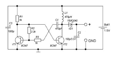
DC to DC converter 1 5V to 3V Circuit Diagram
Image
A DC-DC converter 1.5V to 3V Circuit Diagram to reduce the voltage is easy, but the situation becomes more complicated when we have to increase the voltage. This simple scheme generates a voltage 3Vdc from 1.5 VDC, which can be a single stack. We can get good results by modifying an multivibrator using two transistors, the frequency converter is approximately 130 kHz. The inductance value can be calculated experimentally. DC / DC converter 1.5V to 3V Circuit Diagram Schottky diode VD1 can be replaced by any other similar characteristics. For further stabilization of the output voltage can be placed one Zener 3V - 3.3V. This scheme can be used to feed a power LED device, a micro-controller, Arduino, etc. .. List of Components R1, R3: 1K R2: 2K2 C1: 470pF C2: 100uF / 3.3V C3: 1000uF L1: 470UH VD1: 15MQ040 VT1, VT2: BC547

Voice Activated Home Automation

Image
Voice recognition is no longer in infancy, especially since Siri just launched on the new iPhone 4S (although similar technology is available on Android too. This project shows you how to use it to automate your home without spending big bucks. The core of this project is a VRBot speech recognition module.  Next, the project creator used some low-cost wireless light switches (you could also use relays).  The VRBot speech recognition module recognizes 32 custom voice commands.  Once a command is recognized, a wireless switch is activated via a radio receiver.  The setup is simple after you spend some time understanding the wireless communication protocol between the different modules.  See the project blog to engineer the whole thing yourself.

24V to 12V 400W DC Inverter Circuit

Image
24V to 12V 400W DC Inverter Circuit Diagram 24V to 12V 20A 400W DC to DC Inverter. Does little to change my PV system 12v 24v me the problem arose of what to do with investors who already had 12V. I was looking for a pattern online and found several schemes with linear regulators 20A, this solution although quite simple, due to the huge losses they have is not advisable. Ideally, a converter switched, high-performance. At the end I found nothing I liked and decided to design my own. Circuit characteristics: Output current: 20A at 12V (15A continuous and 30A Momentary), Input voltage: 18 to 30V DC, Output voltage: 5 to 20V, Operating Frequency: 70kHz, Effectiveness: 95%, 400W maximum power, Protections: Above current (30A) in the F1 circuit, D1 and F1 polarity in the circuit.

Rugged PSU For Ham Radio Transceivers

Image
This rugged power supply is based on the popular LM338 3-pin voltage regulator. The LM338 is capable of supplying 5 A over an output voltage range of 1.2 V to 32 V with all standard protections like overload, thermal shutdown, over-current, internal limit, etc., built in. In this power supply, some extra protections have been added to make it particularly suitable for use with low to medium-power portable and mobile VHF/UHF (ham) and 27 MHz transceivers. Diodes D4 and D5 provide a discharge path for capacitors C1 and C2. Diode D8 protects the supply against reverse polarity being applied to the output terminals. Capacitor C1 assists in RF decoupling and also increases the ripple rejection from 60 dB to about 86 dB. If junction R1-R2 is not grounded by switch S1A, transistor T2 starts to conduct, causing the regulator to switch to zener diode D7 for its reference voltage (13 V). The PSU output voltage will then be 12.3 V. Normally, T2 will be off, however, and the PSU output voltage is ...

Priject of Receiver and Transmitter Low Cost Data Circuit Diagram

Image
Priject of Receiver and Transmitte r Low Cost Data Circuit Diagram. Here are two simple circuits that can be used for transmission and reception of data via RF to UHF frequency (433MHZ). Two circuits are super simple, no special components and has a good performance, but short range. It is set to the frequency of 433MHZ, but nothing prevents that with some modifications it works on other frequencies.  Receiver and Transmitter Low Cost Data Circuit Diagram 1 The range is small, ideal for data transmissions within an environment like office, garage, laboratory, workshop or room. This system of data communications short-range 434MHz can be used in projects of alarms, electronic gates, trigger devices from a distance, Arduino, etc. .. X1 is working on a crystal harmonic (433.92Mhz) and L1 receiver comprises 1.5 turns of wire must be tested diameter and thickness to reach the perfect reception of the transmitter.  Receiver and Transmitter Low Cost Data Circuit Diagram 2 You can mou...

8 Watt Audio Power Amplifier Circuit Diagram

Image
This is the 8 Watt Audio Power Amplifier Circuit Diagram. This amp can be used as a simple booster, the heart of a more complicated amplifier or used as a guitar amp. It is very small and portable unit and can be powered through 12V battery. I built the circuit on a Vero Board and had to add extra inductors, capacitors and resistors to prevent oscillation. Circuit diagram: 8 Watt Audio Power Amplifier Circuit Diagram Parts: R1 = 47K R2 = 2.2R/1W R3 = 220R/1W R4 = 2.2R/1W C1 = 100nF-63V C2 = 10uF-25V C3 = 470uF-25V C4 = 2000uF-25V C5 = 100nF-63V IC1 = LM383 SPKR = 4ohm/8W Notes: IC1 must be installed on a heat sink. C1 is for filtering and to prevent oscillation and should not be omitted. The circuit can be built on a Vero Board, universal solder board or PC board, the PC board is preferred. The circuit draws about 880Ma at 12 V. By swapping the values of R2 and R3; you can turn this amplifier into a guitar amp with no preamp required. If you can't find 2000uF, then replace C4 with ...

Voltage to pulse Duration Converter

Image
This is a simple circuit diagram of Voltage-to-Pulse Duration Converter. This circuit is used to convert voltage into pulse duration by combining a timer IC and an OP Amp. Accuracies to better than 1% can be obtained with this circuit (a), and the output signals (b) still retain the original frequency, independent of the input voltage. Voltage-to-Pulse Duration Converter Circuit Diagram Voltage levels can be converted to pulse durations by combining an op amp and a timer IC.