Posts

Showing posts with the label RF

Simple RF Transmitter for PIR Sensors Circuit Diagram

Image
This is the Simple  RF Transmitter for PIR Sensors Circuit Diagram.

RF Generator 6 GHz Circuit Diagram

Image
RF Generator 6 GHz Circuit Diagram. When we talk about high-frequency, everything seems to be difficult, a simple coil becomes a feat. Doing a search on the Internet found that generator "comb" (comb generator), which is a signal generator that produces multiple harmonics of your input signal. The appearance of the output on a spectrum analyzer resemble a comb, hence the name. Comb generators are simpler to build and seem to work well up to 1 GHz This generator I found surprised me because he was 6 GHz has a crystal oscillator 96 MHz (third overtone), capacitively coupled to a broadband amplifier using IC mar3 and capacitively coupled to a back-to-back diode set low capacitance PIN. According to the creator of this circuit was originally designed to produce a reference signal in the amateur radio band of 2.4 GHz, hence the 96.013 MHz crystal RF Generator 6 GHz Circuit Diagram

Low Cost Electronic Project of RF Synthesizer Uses Generic ICs

Image
Low-Cost Electronic Project of RF Synthesizer Uses Generic ICs . You can design a hardware-based frequency synthesizer with one inexepensive IC and a few passive components. Such synthesizer chips are not always available, however, because they are typically single-sourced and are not in stock with parts distributors. The need for a working circuit in a short time and using common parts prompted the creation of the circuit in this Design Idea. The synthesizer covers the US commercial AM (amplitude-modulation) broadcast band. It tunes in 10-kHz steps from 500 to 1800 kHz, but you can scale the frequencies for other applications. The PLL (phase-locked loop) time base is a 100-kHz, tuning-fork-cut crystal of the same size as those in wrist watches. Using a more common crystal requires some extra parts to scale the frequency. Note that if you attempt to use one of these tiny crystals with a CMOS gate oscillator circuit, however, the circuit will either fail to start or exhibit visible jit...

RF Remote Control Encoder and Decoder Chip Pinouts Explained

Image
Making your own universal remote control systems today is very easy. Such procure the relevant chips, assemble them and here goes, your hi-tech remote control device is working for you. Here we explain a couple RF 433kHz remote control chips especially designed for the purpose. The IC TWS-434 along with its encoder chip HOLTEK’s HT-12E form a high class transmitter circuit, whereas the chip RWS-434 through its complementing decoder IC HT-12D operates as the receiver module. Both of the above modules are able to exchange 4-bits of discrete data for control four external loads separately. With the easy availability of accurate remote control chips, making your own universal remote control modules is today just a matter of few hours. We discuss a couple of compact RF remote control transmitter and receiver modules here using the chips: HT-12E, HT-12D, TWS-434, RWS-434 Making a hi-end professional remote control system at home is a child’s play now. With the advent of micro remote cont...

RF Probe for Multimeter Circuit Diagram

Image
This is the RF Probe for Multimeter Circuit DiagramTo measure the RF voltage in a circuit to convert the signal unless they RF voltmeter. This conversion may be done with a very simple circuit, called a point or RF probe. A tip for RF Multimeter has to be made in a metal box with two connectors, one that receives the RF signal and another that goes to the multimeter.  In the case of this circuit the signal passes through two connectors between them and the RF signal is picked up.This signal passes through a 18 pF capacitor, a diode germanium, a resistor of 47 kOhm, and a bypass capacitor 33 nF. The anode of the diode is connected to the positive lead of the voltmeter and the other to ground. RF Probe for Multimeter Circuit Diagram

144 MHz Simple RF Detector Circuit

Image
This simple circuit helps you sniff out RF radiation from your transmitter, improper joints, a broken wire or poor equipment with RF shielding. The tester is designed for the radio band amateur 2 meter (144-146 MHz in Europe). The instrument has a reading of 4-step LED and an audible alarm for high voltage radiation. The RF signal is received by an antenna and made to resonate by C1-L1. After rectification by the diode D1, the signal is fed to a two transistor Darlington amplifier HighGain, T2-T3. Assuming a 10-inch telescoping antenna using the RF level scale established for the LEDs is as follows: When all the LEDs light, the (optional) UM66 sound / melody generator chip (IC1) also operates and provides an audible alarm. By changing the zener diode values ​​of D2, D4, D6 and D8, the step size and duration of the instrument may change as needed. To operate in other bands of ham or PMR, simply change the network-L1 C1 resonance. For example, a transceiver 5 watt handheld equipped with ...

RF Controlled Home Appliance Circuit

Image
Circuit Description: Transmitter This circuit consists of Transmitter and Receiver section. The circuit can be used to control home appliances within a range of 30 meters. In open area, you can expect a range of 100 meters. The circuit comprises HT12 Encoder and Decode IC's. HT12 Encoder is used in the transmitter (remote) circuit where as HT12E is used in receiver circuit. The Encode IC encodes the 4 bits of data and transmit it serially to to RF Transmitter module. These 433Mhz transmitter and receiver modules operate using ASK Modulation. Receiver: For complete information regarding ASK Modulation, click here The converse operation happens in the receiver section. The serial information is given to the decode section and the ICHT12D decodes the 4 bit data and gives across the data pins. The devices are then connected using the ULN2003 high voltage high current buffer. These are some of the images of my own remote. You can design something like this. I had modified it and soldere...

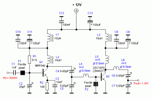
RF Amplifier circuit with 2SC1970 2N4427

Image
RF power amplifier circuit of this work is based on the transistor 2SC1970 and 2N4427. The set output power of 88-108 MHz FM RF Amplifier With 2SC1970 is about 1.3W and the input driver is 30-50mW. RF driver amplifier circuit uses a 2N4427 and its power amplifier using a transistor 2SC1970. At the time of the amplifier circuit tuning FM 88-108 MHz RF Amplifier With 2SC1970 should use the power meter / watt meter or SWR or RF field can also use the meter. RF amplifier circuit can work from the frequency of 88-108 MHz. RF Amplifier Circuit of 88-108 MHz FM RF Amplifier With RF 2SC1970 can radiate far enough. At the time of tuning you should use a 50 Ohm dummy load. For the input signal should be installed to regulate the VR level so as not to over-modulation (30-50mW).

RF amplifier protection

Image
RF amplifier protection I have developed the protection circuit for the EB104 amplifier I am working on, after I finally had some time to design and test a few models. The main requirements have been: - protection in case of high temperature; - protection in case of high SWR; - protection in case of wrong output filter selection; - simple design (i’m a fan of the whole K.I.S.S. rule of thought), able to work in strong electromagnetic fields, reliable, inexpensive. Because i will be using the same directional coupler i have used in the SWR meter (the one made on PCB) wich is directly influenced by the signal frequency, and because i want full HF coverage, i cannot just measure the reflected signal and make a circuit cut the amplifier when it goes over a limit; on 28Mhz the coupler generates roughly 4 times more voltage that let’s say in 7Mhz. So a system that compares direct and reflected signal and triggers when the latter is percentually too high was needed, therefore an operational a...