Posts

Showing posts with the label Long

Long Delay Stop Switch

Image
Presettable times for train stops in stations are indispensable if you want to operate your model railway more or less realistically according to a timetable. This circuit shows how a 555 timer can be used with a relatively small timing capacitor to generate very long delay times as necessary by using a little trick (scarcely known among model railway electronic technicians): pulsed charging of the timing net-work. Such long delays can be used in hidden yards with through tracks, for instance.  As the timer is designed for half-wave operation, it requires only a single lead to the transformer and one to the switching track or reed contact when used with a Märklin AC system (H0 or H1). The other lead can be connected to any desired grounding point for the common ground of the track and lighting circuits. Circuit diagram : Long-Delay Stop Switch Circuit Diagram As seen from the outside, the timer acts as a monostable flip-flop. The output (pin 3) is low in the quiescent state. If a ...
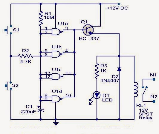
Long duration timer circuit

Image
This timer circuit can be used to switch OFF a particular device after around 35 minutes. The circuit can be used to switch OFF devices like radio, TV, fan, pump etc after a preset time of 35 minutes. Such a circuit can surely save a lot of power. The circuit is based on quad 2 input CMOS IC 4011 (U1).The resistor R1 and capacitor C1 produces the required long time delay. When pushbutton switch S2 is pressed, capacitor C1 discharges and input of the four NAND gates are pulled to zero. The four shorted outputs of U1 go high and activate the transistor Q1 to drive the relay. The appliance connected via the relay is switched ON. When S2 is released the C1 starts charging and when the voltage at its positive pin becomes equal to ½ the supply voltage the outputs of U1 becomes zero and the transistor is switched OFF. This makes the relay deactivated and the appliance connected via the relay is turned OFF. The timer can be made to stop when required by pressing switch S1.

Long range Burglar Alarm Using Laser Torch

Image
Laser torch-based burglar alarms normally work in darkness only. But this long-range photoelectric alarm can work reliably in daytime also to warn you against intruders in your big compounds, etc. The alarm comprises laser transmitter and receiver units, which are to be mounted on the opposite pillars of the entry gate. Whenever anyone enters to interrupt the transmitted laser beam falling on the receiver, the buzzer in the receiver circuit sounds an alarm. The range of this burglar alarm is around 30 metres, which means you can place the transmitter and the receiver up to 30 metres apart. Since the laser torch can transmit light up to a distance of 500 metres, this range can be increased by orienting the phototransistor sensor properly. To avoid false triggering by sunlight, mount the phototransistor sensor such that it doesn’t directly face sunlight. Long-range Burglar Alarm Using Laser Torch Fig. 1: Circuit of laser torch based transmitter The transmitter circuit is powered by 3V DC...

Long Range FM Transmitter

Image
Description The use of transmitters which have a more powerful output than the ‘ flea-power ’ are sometimes required when there are many obstacles in the path of the surveillance transmitter and monitoring station receiver, or the distance between them is too far so as to make a low powered device feasible. Whereas a typical micro transmitter will produce an RF power in the order of just a few milliwatts, i.e. a few thousandths of a watt, the VHF-FM transmitter described has a power output of between around a half and 2 watts, depending on the power source, which may be anywhere between 6 volts and 30 volts d.c. The battery or batteries should be of the alkaline high power type, since the current drain will be found to be relatively higher when compared to microtransmitter current drain. The power output of this device is somewhat proportional to the current drain and so therefore both may be decreased by altering the val...

Long Duration Timer using A Ttiny 2313

Image
This timer circuit is designed to switch on a 12 V load in a solar-powered installation for a preset period at the press of a button. When the period has expired a latching relay disconnects both the load and the controller circuit from the 12 V supply. The length of the period can be configured by making suitable changes to the microcontroller’s source code. When button S1 is pressed a voltage appears across relay coil L1, and the relay switches the load on. Since the relay is a latching type, it remains in this state when the but ton is released. There is now a supply to the 78L05 voltage regulator (a low-dropout type such as the LP2950CZ-5.0 may also be used) and the microcontroller is powered up. In the microcontroller the timer program runs until the configured time interval has elapsed. Around 90 % of the way through the time period LED D2 lights as a warning that the load will shortly be switched off, and this time can also of course be configured by changing the software. When ...

Long range Burglar Alarm Using Laser Torch

Image
Laser torch-based burglar alarms normally work in darkness only. But this long-range photoelectric alarm can work reliably in daytime also to warn you against intruders in your big compounds, etc. The alarm comprises laser transmitter and receiver units, which are to be mounted on the opposite pillars of the entry gate. Whenever anyone enters to interrupt the transmitted laser beam falling on the receiver, the buzzer in the receiver circuit sounds an alarm. The range of this burglar alarm is around 30 metres, which means you can place the transmitter and the receiver up to 30 metres apart. Since the laser torch can transmit light up to a distance of 500 metres, this range can be increased by orienting the phototransistor sensor properly. To avoid false triggering by sunlight, mount the phototransistor sensor such that it doesn’t directly face sunlight.  Long-range Burglar Alarm Using Laser Torch The transmitter circuit is powered by 3V DC. The astable multivibrator built around tim...

Long Interval Pulse Generator

Image
A rectangular-wave pulse generator with an extremely long period can be built using only two components: a National Semiconductor LM3710 supervisor IC and a 100-nF capacitor to eliminate noise spikes. This circuit utilises the watchdog and reset timers in the LM3710. The watchdog timer is reset when an edge appears on the WDI input (pin 4). If WDI is continuously held at ground level, there are not any edges and the watchdog times out. After an interval TB, it triggers a reset pulse with a duration TA and is reloaded with its initial value. The cycle then starts all over again. As a result, pulses with a period of TA + TB are present at the RESET output (pin 10). Circuit diagram: Long-Interval Pulse Generator Circuit Diagram As can be seen from the table, periods ranging up to around 30 seconds can be achieved in this manner. The two intervals TA and TB are determined by internal timers in the IC, which is available in various versions with four different ranges for each timer. To obta...

10 km Long Range Transmitter Circuit 2 meter band

Image
The post explains a 10 km long range transmitter circuit using ordinary components .PCB fabrication also explained. With the increased activity on 2 metres, some who may have contemplated working this band, have possibly been deterred by the cost of a " black box " and the uncertainty of modifying commercial equipment. With this situation in mind, the Author has , designed a simple , easily-built 2m f.m. transmitter, that can be assembled by anyone who can use a soldering iron and small tools whilst possessing a reasonable amount of patience. The completed unit will perform well, being as versatile as the constructor ultimately wishes to make it. An r.f. output of around 1 watts can be expected if the unit is constructed as described but power far in excess of this may be, achieved if the design is regarded as a working basis and the p.a. stage is developed. Construction Procedures for the proposed long range transmitter circuit A simple printed circuit technique is employed...

Long Range FM Transmitter

Image
The use of transmitters which have a more powerful output than the ‘flea-power’ are sometimes required when there are many obstacles in the path of the surveillance transmitter and monitoring station receiver, or the distance between them is too far so as to make a low powered device feasible. Whereas a typical micro transmitter will produce an RF power in the order of just a few milliwatts, i.e. a few thousandths of a watt, the VHF-FM transmitter described has a power output of between around a half and 2 watts, depending on the power source, which may be anywhere between 6 volts and 30 volts d.c. . Circuit diagram : Long Range FM Transmitter Circuit diagram The battery or batteries should be of the alkaline high power type, since the current drain will be found to be relatively higher when compared to microtransmitter current drain The power output of this device is somewhat proportional to the current drain and so therefore both may be decreased by altering the value of R6 to a...

Long Interval Pulse Generator

Image
Long-Interval Pulse Generator Circuit Diagram . A rectangular-wave pulse generator with an extremely long period can be built using only two components: a National Semiconductor LM3710 supervisor IC and a 100-nF capacitor to eliminate noise spikes. This circuit utilises the watchdog and reset timers in the LM3710. The watchdog timer is reset when an edge appears on the WDI input (pin 4). If WDI is continuously held at ground level, there are not any edges and the watchdog times out. After an interval TB, it triggers a reset pulse with a duration TA and is reloaded with its initial value. The cycle then starts all over again. As a result, pulses with a period of TA + TB are present at the RESET output (pin 10).   Long-Interval Pulse Generator Circuit Diagram As can be seen from the table, periods ranging up to around 30 seconds can be achieved in this manner. The two intervals TA and TB are determined by internal timers in the IC, which is available in various versions with four d...

Long range Burglar Alarm Using Laser Torch

Image
Laser torch-based burglar alarms normally work in darkness only. But this long-range photoelectric alarm can work reliably in daytime also to warn you against intruders in your big compounds, etc. The alarm comprises laser transmitter and receiver units, which are to be mounted on the opposite pillars of the entry gate. Whenever anyone enters to interrupt the transmitted laser beam falling on the receiver, the buzzer in the receiver circuit sounds an alarm. The range of this burglar alarm is around 30 metres, which means you can place the transmitter and the receiver up to 30 metres apart. Since the laser torch can transmit light up to a distance of 500 metres, this range can be increased by orienting the phototransistor sensor properly. To avoid false triggering by sunlight, mount the phototransistor sensor such that it doesn’t directly face sunlight. Long-range Burglar Alarm Using Laser Torch Fig. 1: Circuit of laser torch based transmitter The transmitter circuit is powered by 3V DC...