Posts

Showing posts with the label Battery

Flashing LED Battery Status Indicator Circuit
Image
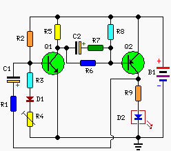
A Battery-status Indicator circuit can be useful, mainly to monitor portable Test-gear instruments and similar devices. LED D1 flashes to attire the user's attention, signaling that the circuit is running, so it will not be left on by mistake. The circuit generates about two LED flashes per second, but the mean current drawing will be about 200µA. Transistors Q1 and Q2 are wired as an uncommon complementary astable multivibrator: both are off 99% of the time, saturating only when the LED illuminates, thus contributing to keep very low current consumption. Circuit operation: The circuit will work with battery supply voltages in the 5 - 12V range and the LED flashing can be stopped at the desired battery voltage (comprised in the 4.8 - 9V value) by adjusting Trimmer R4. This range can be modified by changing R3 and/or R4 value slightly. When the battery voltage approaches the exhausting value, the LED flashing frequency will fall suddenly to alert the user. Obviously, when the batter...

Lithium air battery

Image
4.2.7 Lithium air battery Lithium air battery offers the best energy-to-size ratio compared to mercury, silver oxide and zinc air so far.  Similar in physical appearance as the named cells. Button cell Merits It has a very long shelf life of up to 5 years to reduce capacity to 90% before being de-energized, It has high e.m.f. of about 3.8 volts Uses Backup batteries for low-power computer memories, commonly known as CMOS battery Portable devices where they are soldered into their circuits to last several years. Nb . This battery should not be confused with the lithium ion battery used in cell phones which are secondary battery.  This is covered in KCSE Electricity Form 3 course work under storage batteries.

Versatile Micropower Battery Protector Project

Image
Protect your expensive batteries from discharge damage with this mini-sized electronic cutout switch. It uses virtually no power and can be built to suit a wide range of battery voltages. Main Features Disconnects load at preset battery voltage Automatically reconnects load when battery recharged Ultra-low power consumption (<20ma) Miniature size 10A maximum rating Suitable for use with 4.8-12.5V batteries Transient voltage protection (optional) Suitable for use in... Cars, boats & caravans Security systems Emergency lighting Small solar installations Camera battery packs Many other low-power applications Picture of the project: Back in May 2002, we (Silicon Chip) presented the "Battery Guardian", a project designed specifically for protecting 12V car batteries from over-discharge. This unit has proven to be very popular and is still available from kit suppliers. This new design does not supersede the Battery Guardian – at least not when it comes to 12V car batteries....

Li Ion Battery Charger Circuit Using IC LP2951

Image
The following post explains a very simple yet safe Li-Ion battery charger circuit using just a single IC LP2951. Unlike lead acid batteries one good thing about the Li-Ion batteries is that they can be charged at 1C rate initially. It means the charging current may be as high as the rated AH of the battery at the onset. The design presented in this article can be used for charging a single 3.7V Li-ion cell or a standard cell phone battery externally at a relatively slower rate. The diagram depicts a configuration which was used for charging a Li-Ion cell of a portable stereo unit. The charging specification of the circuit may be summarized as under: Maximum charging current = 150mA Full charge volt = 4.2V +/- 0.025V Charge Current = set at current limit charge mode.    In the given circuit the IC LP2951 becomes the main active component which has been specifically chosen because it is capable of delivering an output voltage that's very stable over temperature. The...

Lead Acid Battery Charge Monitor

Image
As per manufacturer’s data sheets, a 12V rechargeable lead-acid battery should be operated within 10.1V and 13.8V. When the battery charges higher than 13.8V it is said to be overcharged, and when it discharges below 10.1V it can be deeply discharged. A single event of overcharge or deep discharge can bring down the charge-holding capacity of a battery by 15 to 20 per cent. It is therefore necessary for all concerned to monitor the charge level of their batteries continuously. But, in practice, many of the battery users are unable to do so because of non-availability of reasonably-priced monitoring equipment. The circuit idea presented here will fill this void by providing a circuit for monitoring the charge level of lead-acid batteries continuously. The circuit possesses two vital features: First, it reduces the requirement of human attention by about 85 per cent. Second, it is a highly accurate and sophisticated method. Lead Acid Battery Charge Monitor Circuit Diagram:   The cir...

Simple Electronic Project Battery Replacement Power Supply

Image
Here is a simple Electronic Project for battery replacement power supply to build easy.  Your child's battery toy has failed and you have to fix it. Once you have managed to get it apart, the battery compartment is not likely to be connected to the works or the batteries might have gone flat anyway. The solution is this switchable supply which is designed to replace from one to six dry cells. It is not intended to replace the batteries on a permanent basis, as in most cases this is not practical. Battery Replacement Power Supply Circuit Diagram: The heart of the supply is an LM317T adjustable 3-terminal regulator and six trimpots selected by switch S1b. The other pole of the switch, S1a, is used to select taps on the transformer secondary, to minimize power dissipation in the LM317T. The table shows the trimpot settings for the six voltage outputs. Diode D1 and the 10µF capacitor and the LED provide power indication. This has the advantage of constant brightness which would not be...

Nicad Battery charger easy to make

Image
Nicad battery charger , this circuit just use transformer not  CT and  3 LEDs lamp. And its very very simple circuit charger . This circuit constant current LEDs to adjust charging current. It uses LEDs that pass a constant  current about 15 mA for an applied voltage range of 2 to 18 Volt. They can be paralleled to give any multiple of 15 mA and they light up when current is flowing. The circuit will charge single cell at 15 , 30 , or 45 mA , or cells in series up to the rated supply voltage limit about 14 Volt. See schematic below : Click to view larger

Smoke Alarm Battery Life Extender

Image
While smoke alarms are quite cheap devices, the cost of 9V batteries quickly exceeds their purchase price. Added to that is the irritation of random beeps from the alarm as the battery reaches the end of its useful life. This circuit allows typical smoke alarms to be powered from the 12V supply in a burglar alarm while still keeping the standard 9V batteries in place. It extends the 9V battery life to that of its "shelf life" as the battery is only required to drive the smoke alarm in the event the 12V supply is removed or shorted out. Circuit diagram: Smoke Alarm Battery Life Extender Circuit Diagram In normal operation, the LM317 supplies 9.7V and this is fed via diode D2, resulting in just over 9V at the smoke alarm supply terminals. Q1 is not biased on, so the 9V battery is disconnected from the circuit. If the 12V supply is removed, the output of the LM317 will be 0V and Q1 will be biased on via the 4.7kO resistor and thus the smoke alarm will continue to be powered. The...

Battery operation and construction

Image

Portable Battery Charger Circuit

Image
This circuit was designed to charge Nicad battery packs in the range of 4.8 to 15.6 V from a convenient remote power source , such as automobile battery. When power is first applied to the circuit applied to the circuit , a small bias current supplied by R1 via winding L1 , starts to turn on the transistor TR1. This forces a voltage across L2 and the positive feedback given by the coupling of L1 and L2 causes the transistor to turn hard on , applying the full supply across L2. The base drive voltage induced across L1 makes the junction the necessary base current to hold Q1 on. Component List Resistor R1 = 1M R2 = 120R R3 = 10R R4 = 39R Capacitor C1 = 100uF 25V C2 = 0.01uF C3 = 4700pF C4 = 100uF 25V Diode D1 = 1N4148 D2 = BYV27-5 D3 = BYV27-5 Transistor Q1 = ZTX650 Transformer L1 = 12T 36awg L2 = 13T 36awg L3 = 20T 30awg L4 = 40T 30awg Core FX3437 with gap of 0.08mm Former DT2492

Scalable 12V Solar Power System and Battery Charge Controller

Image
An unconventional, scalable high efficiency 12V solar power system and battery charge controller with low voltage cutout to protect the battery. (ideal for systems of 50W or less). The most common solar charger consists of a Schottky diode to prevent the battery from draining into the PV panel and a shunt regulator that effectively short circuits the panel once the battery is fully charged. One problem with this approach is diode losses and the resulting heat. If a 50W 12V panel supplies 4A to the battery, the Schottky diode will drop about 0,4V across it dissipating about 1,6W of heat. This requires a heat sink and loses power to heat. The problem is that there is no way of reducing the volt drop, paralleling diodes may share current, but the 0,4V will still be there. The circuit uses a MOSFET in stead of the usual diode and the primary power loss is resistive. [ ]

How to Reuse Old Cell Battery for LED lighting

Image
Normally cell batteries have a shelf life of 2 to 5 years under normal use . After that time we have to replace them . Nowadays there replacement batteries which are cheap, but these batteries last for much less cost only months. An easy solution is to use batteries in a circuit that requires less current , we can use them for lighting LEDs .  How to Reuse Old Cell Battery for LED lighting 

Low Cost Low State Car Battery Indicator

Image
Here is very simple low-cost electronic circuit project of low state car battery indicator circuit. This electronic circuit diagram designed using few common electronic parts. This low state battery electronic project can be used to monitor car battery voltage. Low-Cost Low State Car Battery Indicator Circuit Diagram: The warning light LED indicates when battery indicates battery voltage falls bellow level set by 10k potentiometer, if the battery is defective or needs charging if cranking drops battery voltage bellow preset safe limit. This circuit project is very simple so it not requires some other explanation.

Heavy Duty But Low Cost Battery charger

Image
This is a heavy duty but low-cost Electronic Circuit . The operation amplifier A1 directly drives the VN64GA with the error signal to control the output voltage. Peak rectifier Dl, CI supplies error amplifier A1 and the reference zener. This extra drive voltage must exceed its source voltage by several volts for the VN64GA to pass full load current. Heavy Duty But Low-Cost Battery charger Circuit Diagram: The output voltage is pulsating dc which is quite satisfactory for battery charging. To convert the system to a regulated dc supply, capacitor C2 is increased and another electrolytic capacitor is added across the load. The response time is very fast, being determined by the op-amp. The 2N4400 current limiter circuit prevents the output current from exceeding 4.5 A. However, maintaining a shorted condition for more than a second will cause the VN64GA to exceed its temperature ratings. A generous heat sink, on the order of 1°C/W, must be used.

Battery powered Headphone Amplifier

Image
Low distortion Class-B circuitry 6V Battery Supply Some lovers of High Fidelity headphone listening prefer the use of battery powered headphone amplifiers, not only for portable units but also for home "table" applications. This design is intended to fulfil their needs and its topology is derived from the Portable Headphone Amplifier featuring an NPN/PNP compound pair emitter follower output stage. An improved output driving capability is gained by making this a push-pull Class-B arrangement. Output power can reach 100mW RMS into a 16 Ohm load at 6V supply with low standing and mean current consumption, allowing long battery duration. The single voltage gain stage allows the easy implementation of a shunt-feedback circuitry giving excellent frequency stability. Battery-powered Headphone Amplifier Circuit diagram Notes: For a Stereo version of this circuit, all parts must be doubled except P1, SW1, J2 and B1. Before setting quiescent current rotate the volume control P1 to t...

Nicad Battery charger easy to make

Image
Nicad battery charger , this circuit just use transformer not  CT and  3 LEDs lamp. And its very very simple circuit charger . This circuit constant current LEDs to adjust charging current. It uses LEDs that pass a constant  current about 15 mA for an applied voltage range of 2 to 18 Volt. They can be paralleled to give any multiple of 15 mA and they light up when current is flowing. The circuit will charge single cell at 15 , 30 , or 45 mA , or cells in series up to the rated supply voltage limit about 14 Volt. See schematic below : Click to view larger

USB powered battery charger circuit

Image
At this time I will share about the series used in the usb to charge battery. Issued voltage 4.7 Volt to 5 Volt DC suitable for battery charge the phone, as well as other batteries.  Below is a circuit where the voltage is removed the usb on the computer will be strengthened by several components so that the voltage used to charge batteries more powerful and filtered, and will make it more durable and long lasting. Part List : R1 = 1 K R2 = 330 R R3 = 4K7 R4 = 300 R R5 = 27R D1 = 4.7 volt zener /1W C1 = 100uF/16V Q1 = BC548 Q2 = BC558A

Simple Car Battery Voltage Monitor Circuit

Image
This circuit is used to monitor the battery voltage to display a dual-colored LED status of the battery to. If the LED “green”battery voltage exceeds 11.9 volts. If the yellow LED , battery voltage 11.9 to 11.5 volts. If the LED is “red” If the battery voltage below 11.5 volts. You can of course change the trigger points by the trimmer resistors and / or changing the value of the resistors in the divider. A dual op amp is used as a comparator. The green LED on the board, until the voltage exceeds 11.5 volts. The red LED illuminates when the voltage falls below 11.9 volts to the circuit. Therefore, in the 11.9 to 11.5 volts, both LEDs are on, producing a slightly yellow color. When the voltage falls below 11.5 V, the green LED , and now only the red LED flashes to indicate low voltage. Parts List R1=1K2 R2-3-4=680R R5=15K R6=10K R7-8-9-10=1K IC1=LM324 D1=5V6 /0.5W Zener D2-3-4-5=LED RV1=10K trimmer  Is recommended that multi-shaper for V1 and V2. Muti-trimmer makes it much easi...

Battery Equality Monitor

Image
Almost all 24V power systems in trucks, 4WDs, RVs, boats, etc, employ two series-connected 12V lead-acid batteries . The charging system can only maintain the sum of the individual battery voltages. If one battery is failing, this circuit will light a LED. Hence impending battery problems can be forecast. The circuit works by detecting a voltage difference between the two series connected 12V batteries. Idle current is low enough to allow the unit to be permanently left across the batteries. Circuit Diagram Parts: R1 = 2.K R2 = 4.7K R3 = 39K R4 = 39K R5 = 1.5K R6 = 1.5K Q1 = BC547 Q2 = BC547 Q3 = BC557 D1 = 3mm Red LED D2 = 3mm GreenLED B1 = DC 12 Volt B2 = DC 12 Volt

Zapper Refurbisher Ni Cad Battery Circuit Diagram

Image
Zapper Refurbisher Ni-Cad Battery Circuit Diagram. Batteries and Nickel Cadmium, or simply Ni-Cad NiCad NiCd or sometimes do not work as expected, has no voltage or current, can not be recharged, it means that the battery is internally shorted or partially damaged. You can retrieve this battery in many ways, either by chemical or electrical recovery. One is simpler and recondition the Ni-Cad battery using a zapper circuit. This circuit restores the Ni-Cad battery short circuit, forcing a high current flow to burn the dirt inside. The resistance of 120 ohm per 10W is used to limit the load current of the capacitor. After zapping the battery goes to the load position, the charging process will take a long time and is indicated by the LED, which will gradually increase the brightness intensity until stable, so when the battery is fully charged. The power supply for the circuit can be made ​​from a small transformer 350 mA to 1 A with a half-wave rectifier or full wave. Zapper Refurbish...