Priject of Receiver and Transmitter Low Cost Data Circuit Diagram
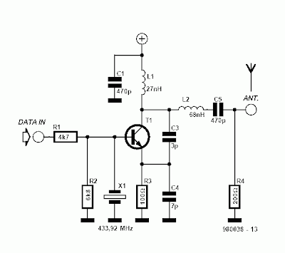
Priject of Receiver and Transmitter Low Cost Data Circuit Diagram. Here are two simple circuits that can be used for transmission and reception of data via RF to UHF frequency (433MHZ). Two circuits are super simple, no special components and has a good performance, but short range. It is set to the frequency of 433MHZ, but nothing prevents that with some modifications it works on other frequencies.
Receiver and Transmitter Low Cost Data Circuit Diagram 1

The range is small, ideal for data transmissions within an environment like office, garage, laboratory, workshop or room. This system of data communications short-range 434MHz can be used in projects of alarms, electronic gates, trigger devices from a distance, Arduino, etc. .. X1 is working on a crystal harmonic (433.92Mhz) and L1 receiver comprises 1.5 turns of wire must be tested diameter and thickness to reach the perfect reception of the transmitter.
Receiver and Transmitter Low Cost Data Circuit Diagram 2

You can mount two of each and create a full duplex transceiver module, ie, it transmits and receives data at the same time.
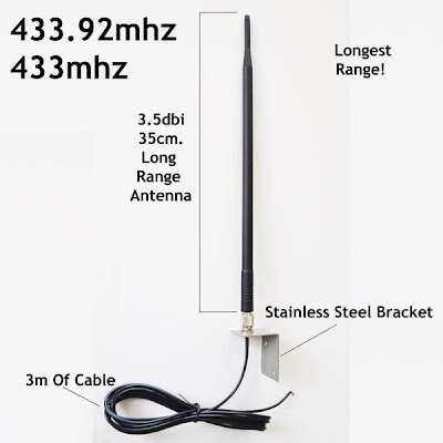
With a suitable antenna it is possible to improve the performance of receiver, transmitter.

Sourced by : Circuitsstream


Comments
Post a Comment