Posts

Showing posts with the label 6V

6V Ultra Bright LED Chaser Circuit Diagram

Image
This is a spectacular but completely useless project. It lights Ultra-Bright LEDs in a sequence and each LED flashes brightly very briefly. The LEDs light-up going around and around since they are mounted in a circle (on a CD), then they pause before chasing again. The very brief flash of each LED (15ms) and the pauses (1 second) reduce the average current so the battery should last a long time.   For user convenience, this project has a stepper speed control and a brightness control. At slower speeds and/or reduced brightness, the battery’s life is extended considerably. At full brightness, the LEDs flash extremely brightly. More than one of this project grouped together occasionally synchronize, lighting the whole room for a moment. Operation At maximum speed, the LEDs don’t appear to flash, instead they appear to move from one lighted one to the next, around and around. They rotate completely for 4 rotations in two seconds, and then turn off for a one second pause then rep...
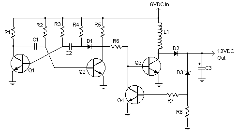
Electronical 6V to 12V Converter Circuit Diagram

Image
      This is the Simple Electronically 6V to 12V Converter Circuit Diagram. This inverter circuit can provide up to 800mA of 12V power from a 6V supply. For example, you could run 12V car accessories in a 6V (British?) car. The circuit is simple, about 75% efficient and quite useful. By changing just a few components, you can also modify it for different voltages.  Electronical 6V to 12V Converter Circuit Diagram Parts R1, R4           2    2.2K 1/4W Resistor    R2, R3           2    4.7K 1/4W Resistor    R5    1            1K 1/4W Resistor    R6    1            1.5K 1/4W Resistor    R7    1            ...

Simple 6V charger battery circuit

Image
This is very simple charger 9V - 30V battery charger with main operation by IC LM317L and 2N222 transistor. Direct input DC voltage , the recomended capacitor is 1000uf. It can be filtering Output voltage and make long-lasting battery. And easy to make this circuit , without using the PCB would be able to. See the Charger Schematic and troubleshooting below : If it can't working , then the mistakes and keeping the following : Check input voltage, whether working or not. Check the installation of the pins of components. Chek transistor , at input voltage , base , and output voltage. Check IC input voltage and output voltage , there or not. Thank  you 4 visiting my blog.