Posts

Showing posts with the label 5V

DC to DC converter 1 5V to 3V Circuit Diagram
Image
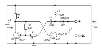
A DC-DC converter 1.5V to 3V Circuit Diagram to reduce the voltage is easy, but the situation becomes more complicated when we have to increase the voltage. This simple scheme generates a voltage 3Vdc from 1.5 VDC, which can be a single stack. We can get good results by modifying an multivibrator using two transistors, the frequency converter is approximately 130 kHz. The inductance value can be calculated experimentally. DC / DC converter 1.5V to 3V Circuit Diagram Schottky diode VD1 can be replaced by any other similar characteristics. For further stabilization of the output voltage can be placed one Zener 3V - 3.3V. This scheme can be used to feed a power LED device, a micro-controller, Arduino, etc. .. List of Components R1, R3: 1K R2: 2K2 C1: 470pF C2: 100uF / 3.3V C3: 1000uF L1: 470UH VD1: 15MQ040 VT1, VT2: BC547

uC 5V Power Supply Voltage Monitoring

Image
This circuit is a very simple voltage monitoring device for +5V VCC supply lines. It can be used to monitor the power supply of a microcontroller (uC) by indicating when the supply level raises above a pre-defined value. The output of the circuit can interface directly to digital logic, reset the microcontroller or turn off the connected microcontroller circuitry before it goes toasted owing to an improper power supply voltage. The ‘proof of concept’ is verified using the eternal single supply dual operational amplifier LM393. However, feel free to try other possible alternatives like LM2903, LM193, etc. The LM393 consist of two independent voltage comparators that are designed to operate from a single supply over a wide range of voltages (2V-36V). The outputs can be connected to other open-collector outputs to achieve wired-AND relationships. The comparator compares two voltages, IN1 at the inverting (–) input and IN2 at the inverting (+) input. When IN2 < IN1, the comparator outpu...

5V 10A Switching Regulator by L4970A Circuit Diagram

Image
Circuit Diagram Description Friends that seek 5V 10A power supply circuit small-sized and build easy. I begs for to advise this circuit. It is 10A switching regulator by use IC L4970A. Then build easy as an example integrated readymade circuit. Important point be power supply input must have 10A current sizes then can give power get enough. The detail is other of the circuit almost must not fine to decorate anything. If friends take an interest try seek buy the integrated circuit and other equipment. come to try build immediately yes. Image Source www.st.com 

5V 2A Dc Converter Using LT3980

Image
Using LT3980 manufactured by Linear Technology can be designed a very simple 5 volts dc converter circuit. 5V 2A Dc Converter Circuit Diagram The LT3980 has an adjustable frequency from 100kHz to 2.4MHz and accepts input voltages up to 58V . The transient voltage of the LT3980 is around 80 volts . The maximum output current which can be delivered by the LT3980 monolithic buck switching regulator is around 2 Amps . Main features of the LT3980 monolithic buck switching regulator are : wide input range from 3.6V to 58V , overvoltage lockout protects circuits through 80V transients , 2A Maximum Output Current , low ripple (<15mVP-P) Burst Mode, aAdjustable switching frequency: 100kHz to 2.4MHz ,low shutdown current: IQ < 1μA, thermal protection, Soft-Start Capability .

LT3582 12 DC 5V to 12V DC Converter Circuit Diagram

Image
Using LT3582-12 dual channel DC DC converter integrated circuit, manufactured by Linear Technology, can be designed a very simple step up dc converter. This 5 to 12V c converter electronic project provide both positive and negative outputs required in many biasing applications such as active matrix OLED (organic light-emitting diode)displays as well as CCD (charge coupled device) applications. LT3582-12 DC 5V to 12V DC Converter Circuit Diagram The LT3582 offer an I2C interface that can dynamically program output voltages, power sequencing and output voltage ramps as the application requires. The LT3582’s positive output voltage can be set between 3.2V and 12.775 in 25mV steps, whereas the negative output can be set between -1.2V and -13.95V in 50mV steps. The LT3582-12 is preconfigured with ±12V output, requiring no future programming.

1 5V to 5V 12V DC DC Converter with LT1073

Image
 1.5V to 5V/12V DC/DC Converter with LT1073 Circuit Small 1.5V to 5V or 12V DC/DC converter with LT1073 chip. The IC is available in three different versions, depending on output voltage. Two with fixed output voltage of 5V and 12V, and the most interesting that can be adjusted. The adjustment is done through a voltage divider with two resistors, of mass, output and Terminal 8, internally connected to the voltage comparator IC, which is responsible for stabilizing the output voltage.