Posts

Showing posts with the label timer

Long duration timer circuit
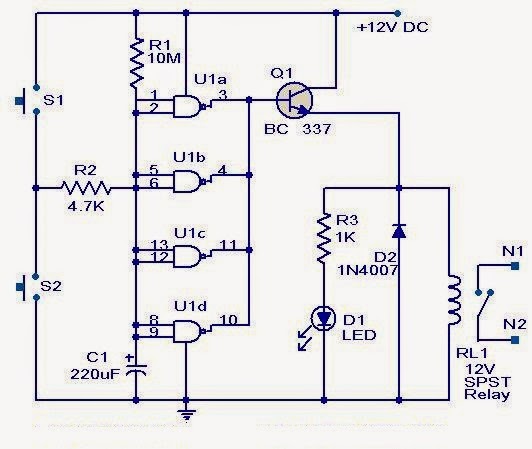
Image
This timer circuit can be used to switch OFF a particular device after around 35 minutes. The circuit can be used to switch OFF devices like radio, TV, fan, pump etc after a preset time of 35 minutes. Such a circuit can surely save a lot of power. The circuit is based on quad 2 input CMOS IC 4011 (U1).The resistor R1 and capacitor C1 produces the required long time delay. When pushbutton switch S2 is pressed, capacitor C1 discharges and input of the four NAND gates are pulled to zero. The four shorted outputs of U1 go high and activate the transistor Q1 to drive the relay. The appliance connected via the relay is switched ON. When S2 is released the C1 starts charging and when the voltage at its positive pin becomes equal to ½ the supply voltage the outputs of U1 becomes zero and the transistor is switched OFF. This makes the relay deactivated and the appliance connected via the relay is turned OFF. The timer can be made to stop when required by pressing switch S1.

555 timer chip tester

Image
IC 555 timer tester is a simple circuit that serves to test the condition of IC 555. 555 timer circuit tester, in principle, start the timer 555 in astable multivibrator mode. As an indicator of the status of the timer 555 good condition or damaged to use 2 pieces LED which will light up in a blink alternately when the timer 555 in good condition.  And only one will turn on or off all the timer 555 when the condition is broken. 555 timer circuit tester is powered using 9 Volt DC voltage source. Complete circuit tester 555 as follows. Tester schematic How to use 555 timer tester is in conjuction with IC 555 to test the existing IC socket according to the orderbutton. Then activate the power switch to begin testing the 555 timer ic. Then live we observe the LED indicators 2buah before, whether flashing alternately (good) or not blink or even die all (timer 555 damaged).

PWM controller with 555 timer chip

Image
IC Timer 555 has a basic PWM controller with pulse width control feature 0 .. 100% which is controlled using the R1, at the time of controlling the oscillator frequency relatively stabi so it may be used to build the Simple PWM controller. Frequency of Simple PWM controller 555 depending on the value of R1 and C1, values ​​shown R1 and C1 will form the output with a frequency of 170 to 200 Hz. Diode-diode used in the Simple PWM controller With this 555 can use a 1N4148. R2, R3 and C3 form a giver triger circuit beginning at the reset IC 555 for 2 seconds. If you want to use a series of Simple PWM controller 555 with the V + not +12 V, it does not matter to raise tilapia R2 where (V + * R2) / (R2 + R3) is about 2, because it limits the signal level reset is 0.5 .. 1V. If you do not do that, then signal the kickstart to get too close to the limit reset signal reception. PWM controller circuit Q output of 555 on the Simple PWM controller circuit 555 is used for driver PWM pulse, so that t...