Posts

Showing posts from November, 2017

How to build Analog Milliamp Meter Used as Voltmeter

Image
A milli Amp analog meter often used along with audio system can be easily converted into a decent volt meter, all that is needed is an understanding of the requirement and the meter. In case a 10V full scale meter is to be designed, then a 10K resistance is to be put in series with the meter coil so that for an applied voltage of 10V a meter can receive 1milliAmp only. The meter itself has an internal resistance and if that is measured properly then in actual practice the resistor to be connected in series shall be having a value of 1000 ohms – IR (internal resistance of the meter). When we measure smaller voltage then this internal resistance of the meter plays a significant role, say for this particular case the internal resistance is 86 ohms, hence, for a I.V. full scale meter the value of the external resistance would be (1000-86) 914 ohms. The milli amp meter can also be used as an Amp meter of higher currents by adding shunt resistances. This is being achieved by simple net...

Dual channel electronic volume controller

Image
General Description: The BA3853BFS is a dual-channel electronic volume controller built around a low-noise, low-distortion VCA. It is suited for car-audio applications, and has performance that rivals mechanical-type volume controllers. In addition to volume control, the IC includes all functions required for controlling sound quality, to allow more compact designs with far fewer components. Circuit diagram: Dual-channel electronic volume controller Datasheet for BA3853: Download

Geiger Counter Uses Cockroft Walton Multiplier Project

Image
This is a project of Geiger Counter Uses Cockroft-Walton Multiplier circuit diagram. The recent tsunami in Japan and the on-going calamity with the Fukushima nuclear power plant has apparently greatly increased sales of radiation meters, not only in Japan but elsewhere around the world. This device will allow an estimation of the level of radioactivity, being sensitive enough for background radiation monitoring or to provide an estimation of the level of radioactivity from sample objects such as Thorium gas mantles in LPG lamps. The circuit is compatible with several Geiger Muller tubes and three types of indication are provided: the good old-fashioned audible click with each discharge, a flashing LED or an analog meter providing a rough average of radiation levels. Geiger Counter Uses Cockroft-Walton Multiplier Circuit Diagram A normal background count in New Zealand with the smaller GM LND712 tube is around 30 counts per minute, while the larger and more-sensitive LND7312 pancake tub...

DANCING FLOWER

Image
This circuit was taken from a dancing flower. A motor at the bottom of the flower had a shaft up the stem and when the microphone detected music, the bent shaft created the flower wiggle and move. The circuit can reply to a whistle, music or noise.

Schematic diagram of a USB player

Image
Usb series player is an electronic device or electronic circuit that functions as an MP3 player that is stored on a storage device such as USB flash. In this usb circuit using an IC as a modifier of digital voice data into analog so that it can be applied to a headphone, or again through the power amlplifier strengthened so that it can be heard through the speakers. IC used in this circuit using IC PCM2902 as a modifier of a digital data into analog data storage. Below is a schematic diagram of a USB player. Schematic usb player

High and Low Voltage Cut Off with Delay and Alarm

Image
This straight forward circuit will protect electrical appliances from over voltage as well as under voltage. The circuit also produces an alarm when the power supply comes back. An ideal circuit for home to protect your valuable equipments from voltage fluctuations. The same circuit with some modifications can be used  to make a automatic voltage stabilizer. High and Low Voltage Cut-Off with Delay and Alarm Circuit Diagram : When the mains voltage is in the normal level, the voltage at the negative terminal of zener diode D4 will be less than 5.6 Volts. At this condition transistor T1 will not conduct. The same time voltage at the negative terminal of zener diode D5 will be greater than 5.6 and so the transistor T2 will be conducting. The relay will be activated and the green LED will be glowing. When the mains voltage is higher than the set limit the transistor T1 becomes conducting since the voltage at the negative terminal of  D4 is greater than 5.6 V. At the same time transist...

BOSS DS 1 DS1 DS 2 DS2

Image

Flashing LED Battery Status Indicator Circuit

Image
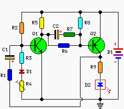
A Battery-status Indicator circuit can be useful, mainly to monitor portable Test-gear instruments and similar devices. LED D1 flashes to attire the user's attention, signaling that the circuit is running, so it will not be left on by mistake. The circuit generates about two LED flashes per second, but the mean current drawing will be about 200µA. Transistors Q1 and Q2 are wired as an uncommon complementary astable multivibrator: both are off 99% of the time, saturating only when the LED illuminates, thus contributing to keep very low current consumption. Circuit operation: The circuit will work with battery supply voltages in the 5 - 12V range and the LED flashing can be stopped at the desired battery voltage (comprised in the 4.8 - 9V value) by adjusting Trimmer R4. This range can be modified by changing R3 and/or R4 value slightly. When the battery voltage approaches the exhausting value, the LED flashing frequency will fall suddenly to alert the user. Obviously, when the batter...

DC to DC converter 1 5V to 3V Circuit Diagram

Image
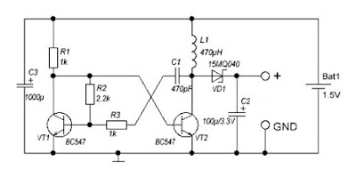
A DC-DC converter 1.5V to 3V Circuit Diagram to reduce the voltage is easy, but the situation becomes more complicated when we have to increase the voltage. This simple scheme generates a voltage 3Vdc from 1.5 VDC, which can be a single stack. We can get good results by modifying an multivibrator using two transistors, the frequency converter is approximately 130 kHz. The inductance value can be calculated experimentally. DC / DC converter 1.5V to 3V Circuit Diagram Schottky diode VD1 can be replaced by any other similar characteristics. For further stabilization of the output voltage can be placed one Zener 3V - 3.3V. This scheme can be used to feed a power LED device, a micro-controller, Arduino, etc. .. List of Components R1, R3: 1K R2: 2K2 C1: 470pF C2: 100uF / 3.3V C3: 1000uF L1: 470UH VD1: 15MQ040 VT1, VT2: BC547

Voice Activated Home Automation

Image
Voice recognition is no longer in infancy, especially since Siri just launched on the new iPhone 4S (although similar technology is available on Android too. This project shows you how to use it to automate your home without spending big bucks. The core of this project is a VRBot speech recognition module.  Next, the project creator used some low-cost wireless light switches (you could also use relays).  The VRBot speech recognition module recognizes 32 custom voice commands.  Once a command is recognized, a wireless switch is activated via a radio receiver.  The setup is simple after you spend some time understanding the wireless communication protocol between the different modules.  See the project blog to engineer the whole thing yourself.

24V to 12V 400W DC Inverter Circuit

Image
24V to 12V 400W DC Inverter Circuit Diagram 24V to 12V 20A 400W DC to DC Inverter. Does little to change my PV system 12v 24v me the problem arose of what to do with investors who already had 12V. I was looking for a pattern online and found several schemes with linear regulators 20A, this solution although quite simple, due to the huge losses they have is not advisable. Ideally, a converter switched, high-performance. At the end I found nothing I liked and decided to design my own. Circuit characteristics: Output current: 20A at 12V (15A continuous and 30A Momentary), Input voltage: 18 to 30V DC, Output voltage: 5 to 20V, Operating Frequency: 70kHz, Effectiveness: 95%, 400W maximum power, Protections: Above current (30A) in the F1 circuit, D1 and F1 polarity in the circuit.

Rugged PSU For Ham Radio Transceivers

Image
This rugged power supply is based on the popular LM338 3-pin voltage regulator. The LM338 is capable of supplying 5 A over an output voltage range of 1.2 V to 32 V with all standard protections like overload, thermal shutdown, over-current, internal limit, etc., built in. In this power supply, some extra protections have been added to make it particularly suitable for use with low to medium-power portable and mobile VHF/UHF (ham) and 27 MHz transceivers. Diodes D4 and D5 provide a discharge path for capacitors C1 and C2. Diode D8 protects the supply against reverse polarity being applied to the output terminals. Capacitor C1 assists in RF decoupling and also increases the ripple rejection from 60 dB to about 86 dB. If junction R1-R2 is not grounded by switch S1A, transistor T2 starts to conduct, causing the regulator to switch to zener diode D7 for its reference voltage (13 V). The PSU output voltage will then be 12.3 V. Normally, T2 will be off, however, and the PSU output voltage is ...

Priject of Receiver and Transmitter Low Cost Data Circuit Diagram

Image
Priject of Receiver and Transmitte r Low Cost Data Circuit Diagram. Here are two simple circuits that can be used for transmission and reception of data via RF to UHF frequency (433MHZ). Two circuits are super simple, no special components and has a good performance, but short range. It is set to the frequency of 433MHZ, but nothing prevents that with some modifications it works on other frequencies.  Receiver and Transmitter Low Cost Data Circuit Diagram 1 The range is small, ideal for data transmissions within an environment like office, garage, laboratory, workshop or room. This system of data communications short-range 434MHz can be used in projects of alarms, electronic gates, trigger devices from a distance, Arduino, etc. .. X1 is working on a crystal harmonic (433.92Mhz) and L1 receiver comprises 1.5 turns of wire must be tested diameter and thickness to reach the perfect reception of the transmitter.  Receiver and Transmitter Low Cost Data Circuit Diagram 2 You can mou...

8 Watt Audio Power Amplifier Circuit Diagram

Image
This is the 8 Watt Audio Power Amplifier Circuit Diagram. This amp can be used as a simple booster, the heart of a more complicated amplifier or used as a guitar amp. It is very small and portable unit and can be powered through 12V battery. I built the circuit on a Vero Board and had to add extra inductors, capacitors and resistors to prevent oscillation. Circuit diagram: 8 Watt Audio Power Amplifier Circuit Diagram Parts: R1 = 47K R2 = 2.2R/1W R3 = 220R/1W R4 = 2.2R/1W C1 = 100nF-63V C2 = 10uF-25V C3 = 470uF-25V C4 = 2000uF-25V C5 = 100nF-63V IC1 = LM383 SPKR = 4ohm/8W Notes: IC1 must be installed on a heat sink. C1 is for filtering and to prevent oscillation and should not be omitted. The circuit can be built on a Vero Board, universal solder board or PC board, the PC board is preferred. The circuit draws about 880Ma at 12 V. By swapping the values of R2 and R3; you can turn this amplifier into a guitar amp with no preamp required. If you can't find 2000uF, then replace C4 with ...

Voltage to pulse Duration Converter

Image
This is a simple circuit diagram of Voltage-to-Pulse Duration Converter. This circuit is used to convert voltage into pulse duration by combining a timer IC and an OP Amp. Accuracies to better than 1% can be obtained with this circuit (a), and the output signals (b) still retain the original frequency, independent of the input voltage. Voltage-to-Pulse Duration Converter Circuit Diagram Voltage levels can be converted to pulse durations by combining an op amp and a timer IC.

Gas Leakage Alarm

Image
Here is a circuit that can be used to detects the leakage of LPG gas and alerts the user through audio-visual indications. The circuit uses SEN-1327 gas sensor module from RhydoLABZ . Its output goes high when the gas level reaches or exceeds certain point. A preset in the module is used to set the threshold. Interfacing with the Sensor module is connected to circuit through a 4-pin SIP header. The circuit powered by 9V PP3 battery. Zener diode ZD1 is used to convert 9V into 5V DC to drive the gas sensor module.  An MQ-6 LPG gas sensor is used in the gas sensor module. According to its datasheet, it has high sensitivity to propane, butane, isobutene, LPG and natural gas. The sensor can also be used to detect combustible gases, especially methane. This circuit has been tested with LPG gas and was found to work satisfactorily. Whenever there is LPG concentration of 1000ppm (parts per million) in the area, the OUT pin of the sensor module goes high. This signal drives timer IC 555, w...

Variable Resistors

Image
Construction Standard Variable Resistor Photograph © Rapid Electronics Variable resistors consist of a resistance   track   with connections at both ends and a   wiper   which moves along the track as you turn the spindle. The track may be made from carbon, cermet (ceramic and metal mixture) or a coil of wire (for low resistances). The track is usually rotary but straight track versions, usually called sliders, are also available. Variable resistors may be used as a rheostat with  two  connections (the wiper and just one end of the track) or as a potentiometer with all  three  connections in use. Miniature versions called presets are made for setting up circuits which will not require further adjustment. Variable resistors are often called  potentiometers  in books and catalogues. They are specified by their maximum resistance, linear or logarithmic track, and their physical size. The standard spindle d...

Simple Inverter Overload Protector Circuit Diagram

Image
Simple Inverter Overload Protector Circuit Diagram . An overload condition in an inverter may  permanently  damage  the  power transistor array or burn off the transformer. Some of the domestic inverters sold in the market do not feature an overload shutdown facility, while those incorporating this feature come with a price tag.the circuit presented here is an overload detector which shuts down the inverter  in  an  overload  condition.   Inverter Overload Protector With Delayed Auto Rest Circuit Diagram   It  hasthe following desirable features: It shuts down the inverter and also provides  audio-visual  indication  of  the overload condition. after  shutdown,  it  automatically restarts  the  inverter  with  a  delay  of  6 seconds. thus, it saves the user from the inconvenience  caused  due  to  manually resetting the system or runn...

l Problem in dalher connection

Image
Problem in dalher connection QUESTION: Contactors in a Dahlander connection are controlled by a PLC. Very often contactors are welding after a speed changeover commands. No transition times are parameterized into the PLC program. Contactors are electrically interlocked however. ANSWER: Enhanced by unfavorable configurations of line frequency and residual magnetic field of rotor, transient reactions inside the motor occur during a changeover of motor speeds. As a result current peaks arise higher than current peaks during ordinary DOL starting. In the worst case the making capacity of contactors is exceeded with contact welding as a consequence.In order to allow the residual magnetic rotor field in to decay, a transition time of at least 50 ms has to be allowed before the line voltage is re-connected during speed changeovers .....

Inverter Overload Protector With Delayed Auto Rest

Image
An overload condition in an inverter may  permanently  damage  the  power transistor array or burn off the transformer. Some of the domestic inverters sold in the market do not feature an overload shutdown facility, while those incorporating this feature come with a price tag.the circuit presented here is an overload detector which shuts down the inverter  in  an  overload  condition.  Circuit diagram: Inverter Overload Protector With Delayed Auto Rest Circuit Diagram It  hasthe following desirable features: It shuts down the inverter and also provides  audio-visual  indication  of  the overload condition. after  shutdown,  it  automatically restarts  the  inverter  with  a  delay  of  6 seconds. thus, it saves the user from the inconvenience  caused  due  to  manually resetting the system or running around in darkness to reset the system at night. It  permanently  shuts  down  the inverter  and  continues  to  give  audio warning,  in  case  there  are  more  than three  succes...

Ultrasonic Transmitter and Receiver

Image
THE Ultrasonic Transmitter circuit shown in Fig. generates ultrasonic sound waves at a  frequency of 40kHz. The key component is a 555 timer, IC1, which is wired as an astable to produce an output frequency of 40kHz. This stream of electrical signals drives the ultrasonic transmitter transducer TX1. Potentiometer VR1, used as a variable resistor, enables you to make fine adjustment to the frequency when setting up the control system to ensure that TX1 is resonating at its optimum natural frequency, thereby ensuring maximum range. This adjustment is described in the ‘synchronising’ section at the end of the receiver section. Ultrasonic Receiver: The circuit shown in Fig. is designed to receive and process the 40kHz pulse of sound waves generated when the transmitter’s pushswitch is pressed. On the first push the relay is energised, and de-energised on the next push, enabling an electrical device to be switched on and off via the relay contacts. The Receiver circuit comprises the fol...

Long Delay Stop Switch

Image
Presettable times for train stops in stations are indispensable if you want to operate your model railway more or less realistically according to a timetable. This circuit shows how a 555 timer can be used with a relatively small timing capacitor to generate very long delay times as necessary by using a little trick (scarcely known among model railway electronic technicians): pulsed charging of the timing net-work. Such long delays can be used in hidden yards with through tracks, for instance.  As the timer is designed for half-wave operation, it requires only a single lead to the transformer and one to the switching track or reed contact when used with a Märklin AC system (H0 or H1). The other lead can be connected to any desired grounding point for the common ground of the track and lighting circuits. Circuit diagram : Long-Delay Stop Switch Circuit Diagram As seen from the outside, the timer acts as a monostable flip-flop. The output (pin 3) is low in the quiescent state. If a ...

Long duration timer circuit

Image
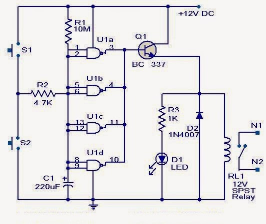
This timer circuit can be used to switch OFF a particular device after around 35 minutes. The circuit can be used to switch OFF devices like radio, TV, fan, pump etc after a preset time of 35 minutes. Such a circuit can surely save a lot of power. The circuit is based on quad 2 input CMOS IC 4011 (U1).The resistor R1 and capacitor C1 produces the required long time delay. When pushbutton switch S2 is pressed, capacitor C1 discharges and input of the four NAND gates are pulled to zero. The four shorted outputs of U1 go high and activate the transistor Q1 to drive the relay. The appliance connected via the relay is switched ON. When S2 is released the C1 starts charging and when the voltage at its positive pin becomes equal to ½ the supply voltage the outputs of U1 becomes zero and the transistor is switched OFF. This makes the relay deactivated and the appliance connected via the relay is turned OFF. The timer can be made to stop when required by pressing switch S1.

Simple 0V to 50 Volt Variable Regulator

Image
A very simple variable power supply circuit can be made using this electronic circuit diagram .This variable regulator circuit will provide an variable regulated output voltage , between 0 and 50 volts . The CA3140 operational amplifier compares the regulator output to a reference voltage , that depends on the R9 value. Simple 0V to 50 Volt Variable Regulator Circuit Diagram  The output voltage will be nominally twice the voltage between the positive input ( noninverting ) of the CA3140 and ground . The unregulated input voltage must be around 60 volts The output voltage can be set between 0 an 50 volts using R9 potentiometer .The 2N3055 transistors must be mounted on a heatsink , to prevent the overheating of transistors .

Burglar Alarm With Timed Shutoff Circuit Diagram

Image
This is a Burglar Alarm With Timed Shutoff Circuit Diagram. When SI (sensor) is closed, power is applied to U2, a dual timer. After a time determined by C2, CI is energized after a predetermined time determined by the value of C5, pin 9 of U2 becomes low, switching off the transistor in the optoisolater, cutting anode current of SCR1 and de-energizing Kl. The system is now reset. Notice that (i6x C2) is less than (R7xC$). The ON time is approximately given by:(R7xC5)-(R6xC2) = Ton  Burglar Alarm With Timed Shutoff Circuit Diagram

Save Your Ears A Noise Meter

Image
‘Hello… HELLO! Are you deaf? Do you have disco ears?’ If people ask you this and you’re still well below 80 , you may be suffering from hearing loss, which can come from (prolonged) listening to very loud music. You won’t notice how bad it is until it’s too late, and after that you won’t be able to hear your favorite music the way it really is – so an expensive sound system is no longer a sound investment. To avoid all this, use the i-trixx sound meter to save your ears (and your neighbor's ears!). With just a handful of components, you can build a simple but effective sound level meter for your sound system. This sort of circuit is also called a VU meter. The abbreviation ‘VU’ stands for ‘volume unit’, which is used to express the average value of a music signal over a short time. The VU meter described here is what is called a ‘passive’ type. This means it does not need a separate power supply, since the power is provided by the input signal. This makes it easy to use: just conne...

Motor driver L298 Circuit

Image
DC motor driver with H-Bridge IC L293D IC H Bridge DC motor driver L298 has two H-Bridge circuit in it, so it can be used to download the drive two DC motors. H Bridge DC motor driver L298 each can deliver currents up to 2A. However, in use, the H Bridge DC motor driver L298 can be used in parallel, so the ability to deliver the H Bridge DC motor driver L298 flow into 4A. The consequences of the installation of H Bridge L298 DC motor driver with the parallel mode, you need 2 pieces Bridge H L298 DC motor driver to control two DC motors using H bridge DC motor driver L298 in parallel mode. H Bridge Pin IC L298 DC motor driver which is connected in parallel operation mode: * OUT1 connected to OUT4. * OUT2 OUT3 linked. * IN1 is connected to IN4. * IN2 connected to IN3. * ENABLE ENABLE A linked to B. OUT1/OUT4 and OUT2/OUT3 associated with DC motors to be controlled. Please note that the output of the L298 does not have a safety diode. Thus, the need to add two diodes - flyback diodes, wit...

Glass Break Alarm Circuit Diagram

Image
This circuit can be used for sounding an alarm to detect the breaking of a glass window by an intruder, even when the intruder ensures there is no sound of the shattered glass. Fig. 1: Circuit of the glass break alarm Circuit and working    Fig. 1 shows the circuit diagram of the glass break alarm. It is built around a piezo element connected across connector CON2, transistor BC549 (T1), timer NE555 (IC1), a piezo buzzer (PZ1) and a few other components. A small piezo element used in the piezo buzzer is used as a sensor. It may be fixed at the centre of the window glass. IC1 is wired in monostable multivibrator mode, which is triggered by the piezo element. Output of IC1 is used to drive piezo buzzer PZ1. LED1 indicates the high-state output at pin 3 of IC1. Time delay can be adjusted by potentiometer VR1. Use an ordinary piezo buzzer at the output to generate a warning sound. This circuit works on 9V-12V DC. When an intruder tries to break the glass, the piezo element generat...

Basic Principles of the LC resonance circuit

Image
If so far you are still confused how the actual origin of the resonance between the capacitor and the inductor is in progress, then the simple circuit above will answer your confusion. By understanding a simple electrical circuit above hopefully we will be able to understand the working principle of a series of more complicated and complex that uses the relationship as a series inductor and capacitors transmitter and receiver. Note the picture above, when the switch SW1 is pressed and released back then obtained by the same signal as in the picture above signal. Initially when SW1 is connected to the voltage supply, the capacitor will make filling fast. Then when SW1 is released charge on the capacitor will be used by the inductor as the supply voltage. In accordance with the general nature of the inductor that the DC signal will be considered ordinary wire inductor such that current flowing quickly through the inductor and the charge on the capacitor decreases rapidly exhausted. Uniqu...

Muscular Bio Stimulator for Treatment of Cellulite Circuit Diagram

Image
This is a very simple circuit of a bio-stimulator Muscular, which has indications for the treatment of cellulite. He sends little shocks through two electrodes, and should take great care when using the stimulator. The muscle stimulator circuit is based on a 555 timer IC. The transformer must be 220 volts to 12 100 to 150 mA and the circuit is connected in reverse. Muscular Bio-Stimulator for Treatment of Cellulite Circuit Diagram The IC 555 to generate pulses at 80 Hz and 150usec by the output voltage of the muscle stimulator device is about 60 volts to 150 volts, but the output current is very small and there is no danger of electric shock. The potentiometer P1 bio-stimulator sets the amplitude of the output pulses' and must be operated by the "patient", starting with the knob fully counterclockwise, then rotating it slowly clockwise until the LED begins to light up. The functional principles of the bio-stimulator is the same commercial bio-stimulator. Parts List: Linea...