Posts
Showing posts from September, 2017
DCF77 to USB Converter
- Get link
- X
- Other Apps
I like the handy DCF77 signal. In this project no clock should use it, instead the computers in my home network should be served by a precise time reference. Due to the fact most other interfaces are no longer available on modern computers, it uses the USB to forward the prepared DCF77 signal to the host.
50W audio amplifier with ICs
- Get link
- X
- Other Apps
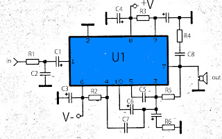
The above amplifier circuit based on IC is STK075G, and another equation that is STK084G, STK085, STK086G. and among ic I mentioned that I recommend using ic high supply voltage and high output power and good quality. You can see every ic datasheet at Alldatasheet.com above. Supply voltage between 20 to 55 Volt DC. Part List R1 = 1K R2 = 100R R3 = 100R R4 = 4.7R R5 = 56K R6 = 47R C1 = 1uF C2 = 470pF C3 = 100uF C4 = 100uF C5 = 1800pF C6 = 1uF C7 = 1800pF C8 = 0.047uF C9 = 100uF U1 = STK075G, STK084G, STK085, STK086G
Quad Audio Amplifier Circuit diagram with TDA7831 4×25W
- Get link
- X
- Other Apps
Quad Audio Amplifier Circuit diagram with TDA7831 4×25W The afterward is a cloister amplifier circuit (amplifier with four inputs and four outputs) based TDA7381. This amplifier is advised for car audio system, but you can additionally use this ambit for added purposes. This ambit has a architecture actual simple and actual accessible to build.
Network Voltage Indicator
- Get link
- X
- Other Apps
Using this schematic can be made a network voltage indicator electronic circuit. If the input voltage is present across the network, the optocoupler transistor is open, T1 is blocked and controlled rectifier, Th1, is in a state of conduction. Since both terminals of the piezoelectric buzzer is at the same potential, buzzer is off. If voltage disappears, the transistor T1 enters the conduction and thus makes the terminal of buzzer to be put on the ground (maintains thyristor conduction state). Network Voltage Indicator Circuit diagram: In this situation, there is a sufficiently large potential difference across the buzzer and D5's to determine that these two elements to indicate AC power loss, both audible and visual. By pressing the reset button current is interrupted by Th1, so thyristor enter in blocking state and the other terminal of the buzzer is connected to ground.
Personal Dressing Safety
- Get link
- X
- Other Apps
1.2 Personal dressing In an electrical workshop, it is always important to be properly dressed. This will provide protection from dangers associated with electricity, moving machine parts, tools and materials. The following dressing is therefore suggested: Shoes Should provide a good rubber grip on the floor and be of suitable top and, if possible, reinforced with steel toe caps to protect the feet against injuries from sharp and heavy objects. Clothing Should either be an overall, a dustcoat or an apron worn to protect the body and personal clothing. They should be short sleeved; long sleeves should be rolled or buttoned up. All buttons should be in place and done up. Neckties should be removed or tucked-in, especially when working with machines, else they might be caught up in the moving parts. Hand Gloves Rubber, plastic or leather gloves should be worn when handling acids, other corrosive substances, as well as hot objects. Helmets These should be worn in areas where there is dange...
Mains Slave Switcher II Circuit Diagram
- Get link
- X
- Other Apps
This is a simple project of Mains Slave Switcher II Circuit Diagram . As a guide, a one-inch reed switch with 40 turns reliably switched on with the current flowing through a 150-watt lamp (approx. 625 mA) but larger reeds may require more turns. If the master appliance draws less current (which is unlikely with power tools) more turns will be required. The reed switch is used to switch on transistor T1 which in turn switches the relay RE1 and powers the slave appliance. Since reed switches have a low mechanical inertia, they have little difficulty in following the fluctuations of the magnetic field due to the alternating current in the coil and this means that they will switch on and off at 100 Hz. Mains Slave Switcher II Circuit Diagram: Mains Slave Switcher II Circuit Diagram C3 is therefore fitted to slow down the transistor response and keep the relay energised during the mains zero crossings when the current drawn by the appliance falls to zero and the reed switch opens. C1 drops...
Victorinox is the most secure memory stick
- Get link
- X
- Other Apps
Victorinox has launched a memory stick design which is, says the company, the most secure of its kind available to the public. The Victorinox memory stick uses several layers of security including fingerprint identification and a thermal sensor. Any attempt to forcibly open it triggers a self-destruct mechanism that irrevocably burns its CPU and memory chip. The data can only be accessed through recognition of your fingerprint or the password. In addition to these functions, the Victorinox Secure also has a bright LED light that will reliably show you the way in the dark. With this tool as well, it goes without saying that you will not have to do without the indispensable Swiss Army Knife functions, such as a blade, nail file with screwdriver end, scissors and key ring. A new version of the device, which will employ e-paper to give users a read-out of its contents, is already in the pipeline. Victorinox say they wanted to create not only a product for today’s modern lifestyle but ...
LA4440 Power Amplifier Circuit
- Get link
- X
- Other Apps
This is a very simple circuit power amplifier with IC LA4440. This circuit is a circuit the first time i learned to make a power amplifier. Power output 2 X 20 Watt with stereo speakers. Minimum Voltage 9 Volt and maximum voltage 24 V. The Circuit is also very easy to make. For novices , this circuit is suitable for use . The material is also readily available at electronics store. See schematic below : The Speaker are matched with woofer speaker with impedance 4 Ohms. And voltage can be stabilized with IC 7812 but must be reinforced such us transistor.
Build a 1 3 32 V 5A Power Supply w Short Circuit Protection by LM338
- Get link
- X
- Other Apps
Project Description This is a very easy to build power supply that is based on LM338 5A adjustable voltage regulator. I am using the supply for a long time, have no problem yet. Only current adjust is missing but I overcome this situation by using an LCD panel ampermeter. There is no PCB for the circuit. I took a 3x16 copper plate and strip the unused areas by a knife. If you want you can use analog meters instead of LCD panels. Notes Use thick wires for connections.When connecting the LM338 to the heatsink use thermal paste. Use external supplies for LCD panels. They can be 9V batteries. The panels I use draws 1mA current and the batteries last sufficiently long time. If you have small transformers which can supply regulated 9V, you can use them. You need separate transformers for each panel!The transformer should be 100 Watt but if you don't need high current you can try transformers that you already have. (I can draw 6A from 100Watt transformer.)If you have ...
TV Remote Jammer Using 555 IC Circuit Diagram
- Get link
- X
- Other Apps
The TV remote control transmits television signals as pulses of frequency around 37.5kHz. Each button on the remote control is pressed or equivalent has a pulse signal codes. This remote transmits pulses of the circuit block of the same frequency as the remote to your TV confuse decoding the transmitted signal. The heart of the circuit is the 555 timer IC in astable circuit works mode.The output series of pulses at a frequency of 18 kHz to 48 kHz by simply adjusting the 5K potentiometer. What you do is adjust the potentiometer until frequeny jives to its distance from the TV or until the signal is ignored by television. TV Remote Jammer Using 555 IC Circuit Diagram
Loewe CRT TV Circuit Diagram
- Get link
- X
- Other Apps
Used ICs: TDA7296 – TDA4653 – BUZ91A(FET) – TEA6422D – TEA6415 – MSP3411 – MC33079 – VPC323 – M27V322-100 EPROM – TS831-3IDT – SDA9488 – TDA9332-N2 – TSA5523M – TDA6111 – LM2574 – TE28F008 – KM416V – STI5500 – STV299B – CS4344 – LM2574M – MAX4546 – STV0056 – TDA6151-5X Schematic Click on the schematics to zoom in
SIMPLE COUNTING CIRCUIT 0 to 99
- Get link
- X
- Other Apps
DIGITAL COUNTING CIRCUIT A simple Digital counting circuit, which will counts from 00 to 99. The counter will incremented by one for each pulse given in the terminal A and B. The pulse can be given by just short circuiting the end points A and B. You can use this circuit for a wide variety of applications such as, for Digital Entry Counter, Speedometer circuit, distance measuring devices etc. CIRCUIT DIAGRAM WORKING PRINCIPLE The 555 timer is wired as an ASTABLE MULTIVIBRATOR, which will generate an output for each pulse given in the terminal A and B. The output is taken from pin 3 and is directly given to the clock input (1) of decoding IC CD4033. CD 4033 is used here as 7 segment Display Driver. The Cout from this IC is given to another CD4033 IC. Which will drive another 7 segment Display. The 7 segment display used here is of Common Cathode type. So the pin 3 is connected to ground. You can increase the number of bits to count in this circuit (99999......) Other useful Links:- INTE...
Circuit Board Checker Circuit Diagram
- Get link
- X
- Other Apps
This little circuit indicates the basic integrity of a printed board, detecting 0V, positive supply voltage from less than 3V to 30V and floating parts. If the probe is floating, as it would be in a broken track, then both LEDs barely light up, since there is no current to drive the transistors, but if the probe touches 0V or a positive voltage one or other lights. A digital signal should light them in proportion to the mark-space ratio whereas the output of a circuit oscillating at a frequency rate below about 20Hz will cause the LEDs to flicker alternatively. The LEDs will illuminate always at a constant intensity, no matter the voltage supply used, because they are fed by a very simple FET constant-current generator (Q1). Circuit diagram: Circuit Board Checker Circuit Diagram Parts: R1 = 22K R2 = 22K D1 = Red LED D2 = Green LED Q1 = BF245 Q2 = BC547 Q3 = BC557 Notes: The Black clip must be connected to the negative ground of the board under test. The Red clip should be connected to ...
USB Power Booster
- Get link
- X
- Other Apps
The USB serial bus can be configured for connecting several peripheral devices to a single PC. It is more complex than RS232, but faster and simpler for PC expansion.Since a PC can supply only a limited power to the external devices connected through its USB port, when too many devices are connected simultaneously, there is a possibility of power shortage. Therefore an external power source has to be added to power the external devices. USB Power Booster Circuit Diagram In USB, two different types of connectors are used: type A and type B. The circuit presented here is an add-on unit, designed to add more power to a USB supply line (type-A). When power signal from the PC (+5V) is received through socket A, LED1 glows, opto-diac IC1 conducts and TRIAC1 is triggered, resulting in availability of mains supply from the primary of transformer X1. Now transformer X1 delivers 12V at its secondary, which is rectified by a bridge rectifier comprising diodes D1 through D4 and filtered by c...
An LCD Clock Kit Suitable for Beginners with Open Source Arduino Firmware
- Get link
- X
- Other Apps
Simpleclock is an easy to assemble attractive 4-digit 7-segment LED display clock with temperature and alarm function. It is available in three display colors: Red, Blue and White. It comes as a kit of through-the-hole parts and can be soldered by any person with basic soldering experience. An attractive acrylic stand is included. [ ]
Push Bike Light Circuit Diagram
- Get link
- X
- Other Apps
Automatic switch-on when it gets dark, 6V or 3V battery operation This design was primarily intended to allow automatic switch-on of push-bike lights when it gets dark. Obviously, it can be used for any other purpose involving one or more lamps to be switched on and off depending of light intensity. Power can be supplied by any type of battery suitable to be fitted in your bike and having a voltage in the 3 to 6 Volts range. The Photo resistor R1 should be fitted into the box containing the complete circuit, but a hole should be made in a convenient side of the box to allow the light hitting the sensor. Trim R2 until the desired switching threshold is reached. The setup will require some experimenting, but it should not be difficult. Circuit diagram: Push-Bike Light Circuit Diagram Parts: R1_____________Photo resistor (any type) R2______________22K 1/2W Trimmer Cermet or Carbon type R3_______________1K 1/4W Resistor R4_______________2K7 1/4W Resistor R5_____________330R 1/4W Resistor (...
10W Audio Power Amplifier
- Get link
- X
- Other Apps
10W PA.The 10 watts power amplifier circuit by transistor describe here is an audio amplifier with output power of 10W.Used as a low frequency class AB Amplifier. Transistor has high output current and very low distortion. 10W Audio Power Amplifier Circuit Diagram: This 10W audio amplifier circuit diagram using Transistor is good for small room or car audio system.This circuit is a general-purpose 10W audio amplifier for moderate-power PA or modulator use in an AM transmitter. With higher voltages and a change in bias resistors,up to 30 W can be obtained.
Capacitor leakage circuit tester
- Get link
- X
- Other Apps
Generally capacitor that complement with television circuit is often leaked. Consequently spots more rugged display disturbing images running. This is not desired by the owner is not it? For those who know about electronics is certainly a problem. They will find the cause and trying to fix it. For it is not uncommon to use multitester a a search tool damage. But for those who do not have a tool that becomes an obstacle . However , for those of you who enetered last category do not sad because they can assemble their own tester. This tool is very simple but very sensitive to the leackage of a capacitor. Schematic Part List Resistor R1____________________________3K3 R2____________________________100K R3____________________________100K Capacitor C1____________________________10uF 150V C2____________________________10uF 150V Diode D1____________________________K-200 D2____________________________K-200 Lamp__________________________Fluorescent Lamp Switch_________________________On/Off How ...
Simple Function Generator Circuit Diagram
- Get link
- X
- Other Apps
This is a simple function generator circuit that can produce the following waveforms: square wave, triangular wave, and sine wave. The circuit's main components are two 1458 IC's. The 1458 is a dual op-amp IC, i.e., an IC that houses two op amps inside it. The circuit uses four op amps, two from each 1458. The bottom-most op amp in Figure 1 is configured as an astable multivibrator, which continuously generates a square wave. Assume that C1 has no charge initially. The voltage at the inverting input is zero, while the voltage at the non-inverting input is very slightly positive (a ratio of the op amp's output offset voltage as determined by R1 and R2). This minute voltage difference at the inputs is enough to cause the op amp's output to swing to 'high'. When the output becomes high, C1 starts charging up. The voltage at the inverting input soon exceeds that at the non-inverting input, forcing the output to swing to 'low', w...
Simple Electronic Project Battery Replacement Power Supply
- Get link
- X
- Other Apps
Here is a simple Electronic Project for battery replacement power supply to build easy. Your child's battery toy has failed and you have to fix it. Once you have managed to get it apart, the battery compartment is not likely to be connected to the works or the batteries might have gone flat anyway. The solution is this switchable supply which is designed to replace from one to six dry cells. It is not intended to replace the batteries on a permanent basis, as in most cases this is not practical. Battery Replacement Power Supply Circuit Diagram: The heart of the supply is an LM317T adjustable 3-terminal regulator and six trimpots selected by switch S1b. The other pole of the switch, S1a, is used to select taps on the transformer secondary, to minimize power dissipation in the LM317T. The table shows the trimpot settings for the six voltage outputs. Diode D1 and the 10µF capacitor and the LED provide power indication. This has the advantage of constant brightness which would not be...
6 to 12 Volt Power Supply Inverter
- Get link
- X
- Other Apps
This inverter circuit can provide up to 800mA of 12V power from a 6V supply. For example, you could run 12V car accessories in a 6V (British?) car. The circuit is simple, about 75% efficient and quite useful. By changing just a few components, you can also modify it for different voltages. Part List: R1, R4 2.2K 1/4W Resistor R2, R3 4.7K 1/4W Resistor R5 1K 1/4W Resistor R6 1.5K 1/4W Resistor R7 33K 1/4W Resistor R8 10K 1/4W Resistor C1,C2 0.1uF Ceramic Disc Capacitor C3 470uF 25V Electrolytic Capcitor D1 1N914 Diode D2 1N4004 Diode D3 12V 400mW Zener Diode Q1, Q2, Q4 BC547 NPN Transistor Q3 BD679 NPN Transistor L1 See Notes MISC Heatsink For Q3, Binding Posts (For Input/Output), Wire, Board source:LINK
Simple USB Relay – I O Modules
- Get link
- X
- Other Apps
After the success of small modules USB – I / O converters – PUSBIO with MCP2200 circuit intended for development and small batch production, which we introduced in Article MCP2200 USB module and I / O , and recently introduced software for USB I / O modules , now the company introduces new modules Pandatron with relays and optocouplers.